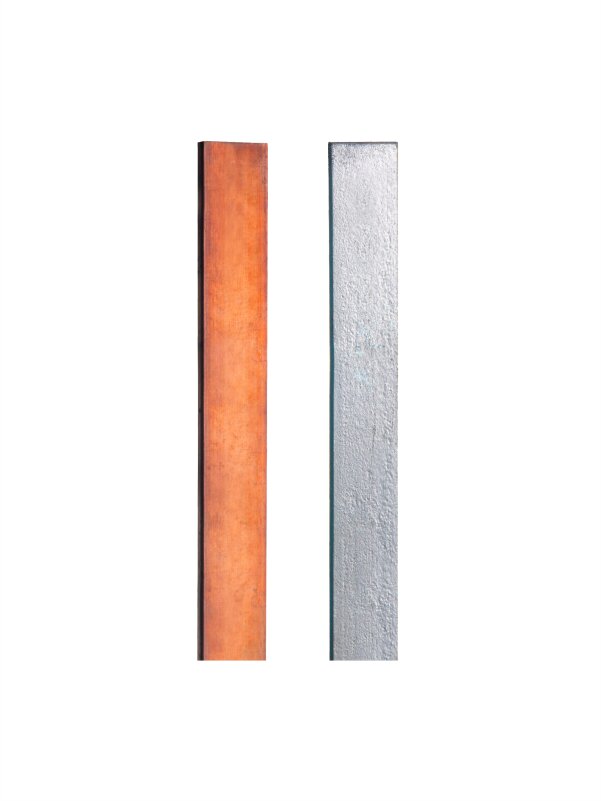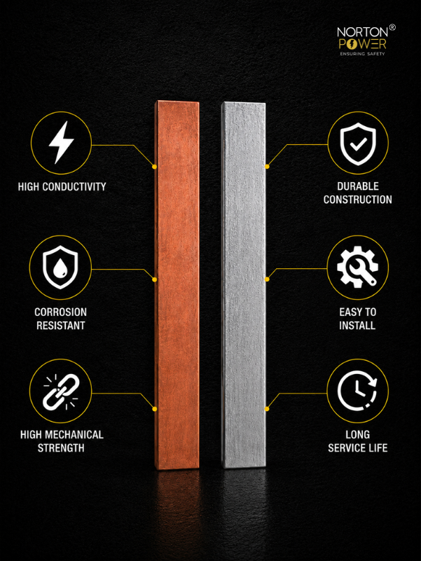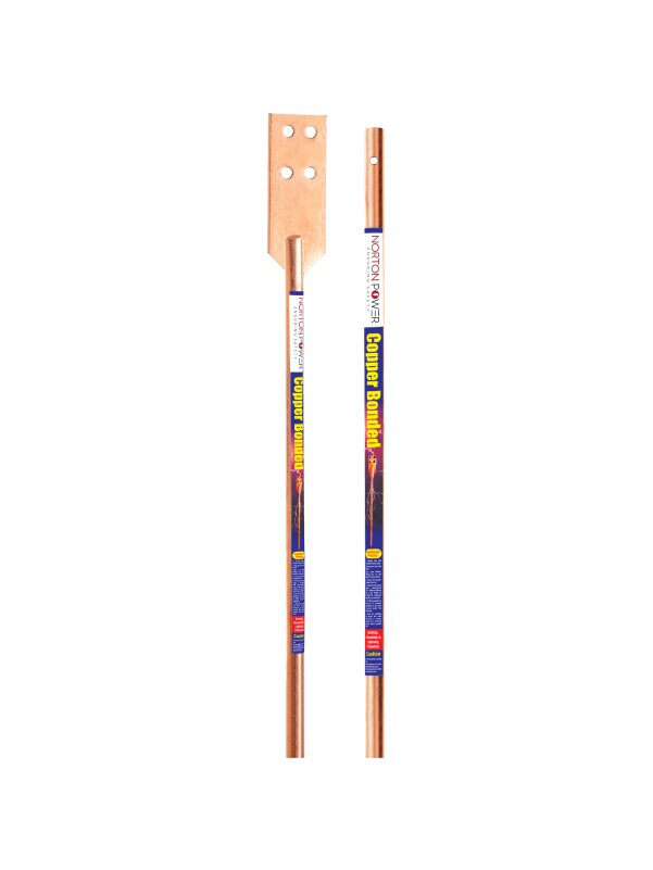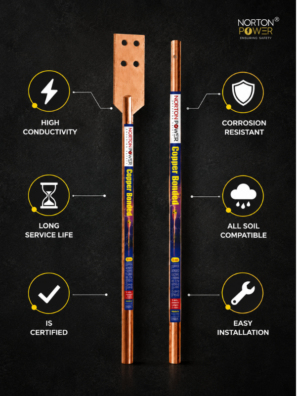
An earthing strip is the flat metal bar that ties an earthing system together, interconnecting earth electrodes into a grid, bonding equipment and structures to that grid, and carrying lightning down-conductor current to the pits. It comes in copper and galvanised iron in a range of standard sizes. This guide covers the sizes, the copper-versus-GI choice, and where the strip is used.
1. What the earthing strip does
- Interconnects earth rods/electrodes into a low-resistance grid.
- Bonds equipment frames, neutrals and structures to the earth.
- Carries lightning and fault current to the earth electrodes.
- Forms the buried ring conductor that itself adds soil contact.
2. Standard sizes (and how to read them)
A strip size like "25 x 3 mm" means 25 mm wide and 3 mm thick, giving a 75 mm² cross-section. Common standard sizes:
| Strip | Cross-section / typical use |
|---|---|
| 25 x 3 mm copper | 75 mm² — lightning down-conductor, small bonding |
| 25 x 6 mm copper | 150 mm² — standard equipment earthing / grids |
| 32 x 6 / 40 x 6 mm copper | 192 / 240 mm² — substation main grids, higher fault current |
| 50 x 6 mm GI | 300 mm² — distribution-grade grids |
| 65 x 8 / 75 x 10 mm GI | High-fault GI grids (sized up for GI conductivity) |
3. Copper vs GI strip
Copper is the default for substations, HV grids and lightning down-conductors, for its conductivity and decades-long corrosion life. GI is acceptable for distribution-grade work in benign soil on a budget, sized up (roughly 1.8x the copper cross-section) to compensate for its lower conductivity. For the fault-current maths behind the cross-section, see the earthing-strip sizing guide.
4. Where the strip is used
- Buried ring conductor connecting all earth pits.
- Risers from the pit chamber up to equipment earth bars.
- Bonding runs to structures, cable trays, panels and services.
- Lightning down-conductors from air terminals to the earth.
5. Burial and joints
Bury the grid strip at about 0.5 m so it contributes its own soil contact; use gentle curves (not sharp bends) on any run carrying surge current; and make joints with the correct lugs/clamps or exothermic welds for buried HV grids. Protect copper-to-GI and copper-to-aluminium joints against galvanic corrosion.
6. How to choose (checks)
- Copper or GI — does it match the site life and fault duty?
- Is the cross-section sized for the actual fault current and clearing time (see the sizing guide), not a default?
- Material grade and purity (electrolytic copper / IS 4759 GI)?
- Cut lengths or coils, and what jointing hardware is supplied?
- For GI: coating thickness and corrosion warranty for your soil?