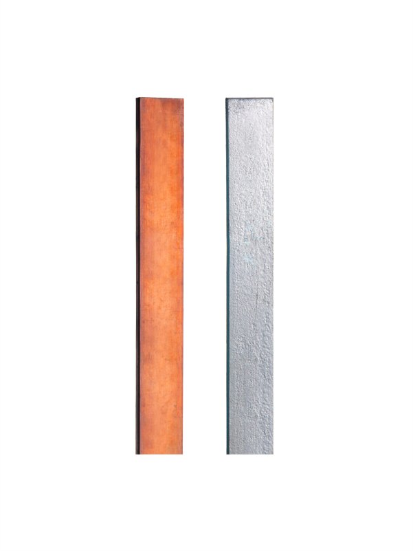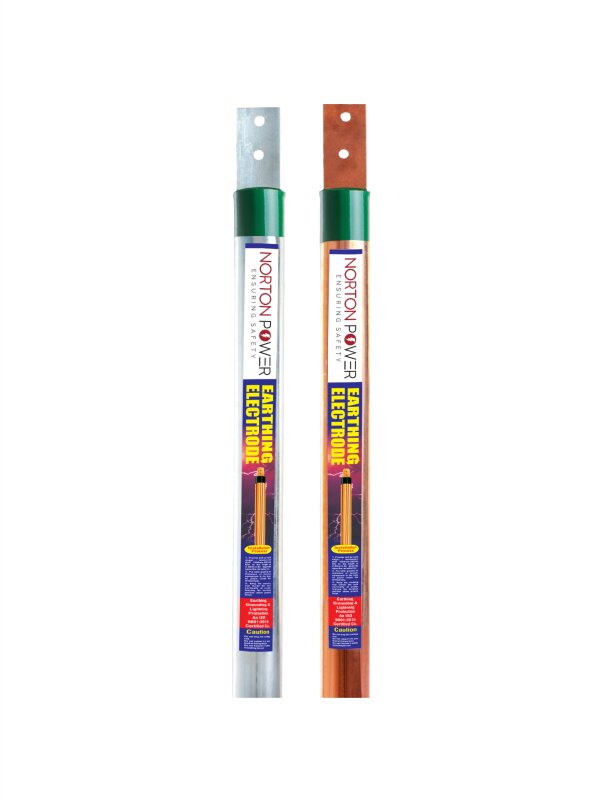
An earthing strip is specified as width x thickness in millimetres. The common GI sizes are 25 x 3, 25 x 6, 32 x 6, 40 x 6, 50 x 6, 50 x 10 and 65 x 10 mm; copper strip is usually 25 x 3, 25 x 6, 32 x 6 and 50 x 6 mm. The right size depends on the fault current it must carry for the clearing time, not on habit. This chart gives the standard sizes and how to choose.
1. GI (galvanised iron) strip size chart
Indicative fault current the strip can carry for one second, from the IS 3043 adiabatic rule (cross-section in square millimetres times about 80 for steel). Size up for longer clearing times.
| GI strip size (cross-section) | Indicative 1 s fault current and typical use |
|---|---|
| 25 x 3 mm (75 sq mm) | About 6 kA - panels and sub-distribution |
| 25 x 6 mm (150 sq mm) | About 12 kA - distribution boards |
| 32 x 6 mm (192 sq mm) | About 15 kA - LT panels |
| 40 x 6 mm (240 sq mm) | About 19 kA - LT earth grids |
| 50 x 6 mm (300 sq mm) | About 24 kA - main earth grid |
| 50 x 10 mm (500 sq mm) | About 40 kA - HT grids |
| 65 x 10 mm (650 sq mm) | About 52 kA - substations and power plants |
2. Copper strip size chart
Copper carries far more current for the same cross-section (the factor is about 205 instead of 80), so a smaller copper strip matches a larger GI one.
| Copper strip size (cross-section) | Indicative 1 s fault current |
|---|---|
| 25 x 3 mm (75 sq mm) | About 15 kA |
| 25 x 6 mm (150 sq mm) | About 31 kA |
| 32 x 6 mm (192 sq mm) | About 39 kA |
| 50 x 6 mm (300 sq mm) | About 61 kA |
3. How to read a strip size
- First number is the width, second is the thickness, both in millimetres (50 x 6 means 50 mm wide, 6 mm thick).
- Cross-section (width times thickness) decides the current it can carry and is what IS 3043 sizes.
- Material matters: copper for high fault current, long life and HV or data work; GI for cost on general LT earthing.
4. How to choose the right size
- Take the fault current and the protection clearing time for the installation.
- Apply the IS 3043 / IEEE 80 rule: cross-section equals fault current times the square root of time, divided by the material factor.
- Round up to the next standard size, then add margin for corrosion over the design life (more margin for GI).
- Match the strip material to the electrodes and joints to avoid bimetallic corrosion.