An ESE (Early Streamer Emission) lightning arrestor only delivers its rated protection radius if it is installed correctly — the right mast height, clean down-conductor routing, and a dedicated low-resistance earth. This is the practical sequence used on Indian projects specified under NF C 17-102.
1. What goes into an ESE installation
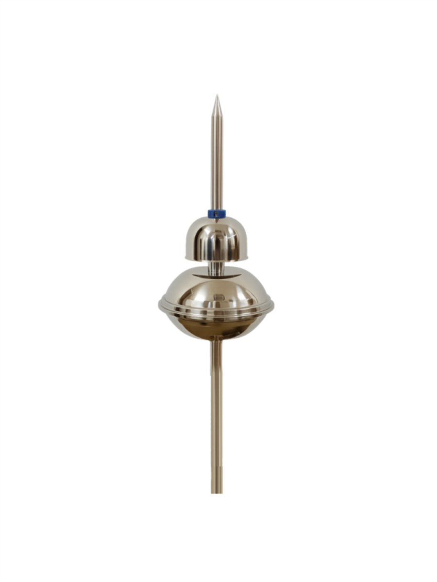
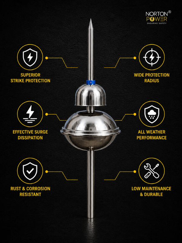
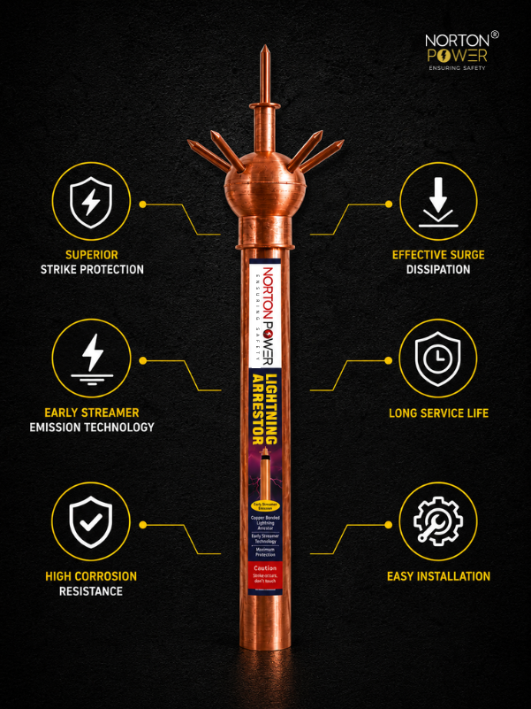
- ESE air terminal (the arrestor head) with its delta-T rating (15 / 25 / 40 / 60 µs).
- Mast — galvanised or stainless, height chosen to deliver the required protection radius.
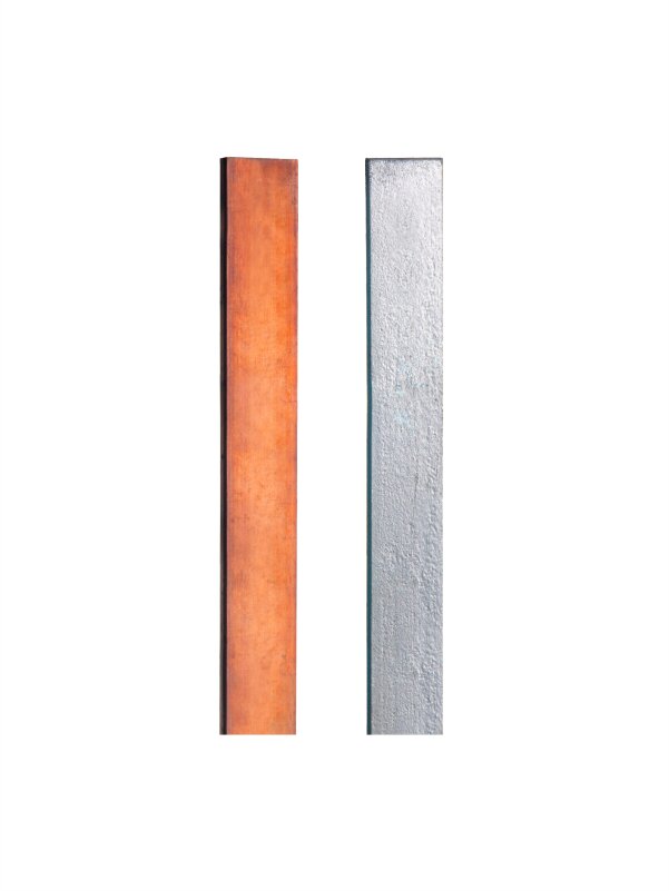
- Two down-conductors (25×3 mm copper tape or 8 mm copper round) routed by the most direct paths.
- Surge-event counter (lightning strike counter) on one down-conductor.
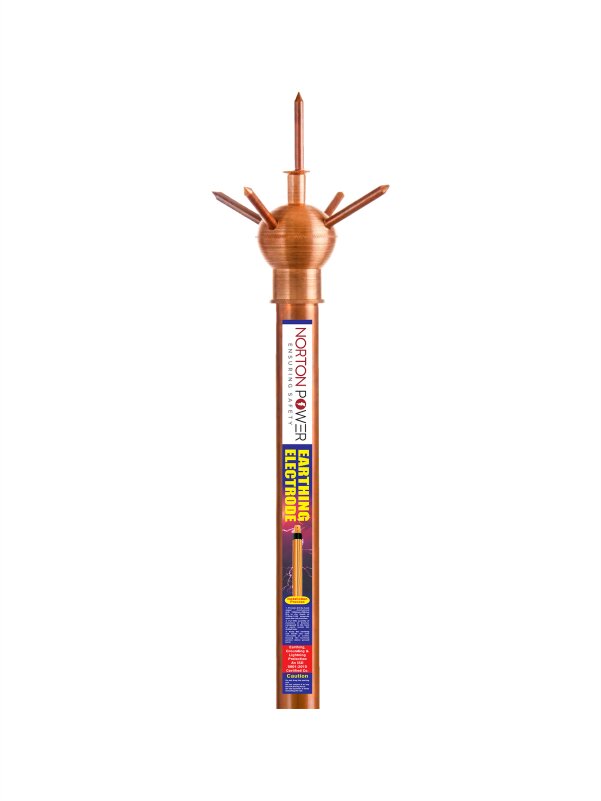
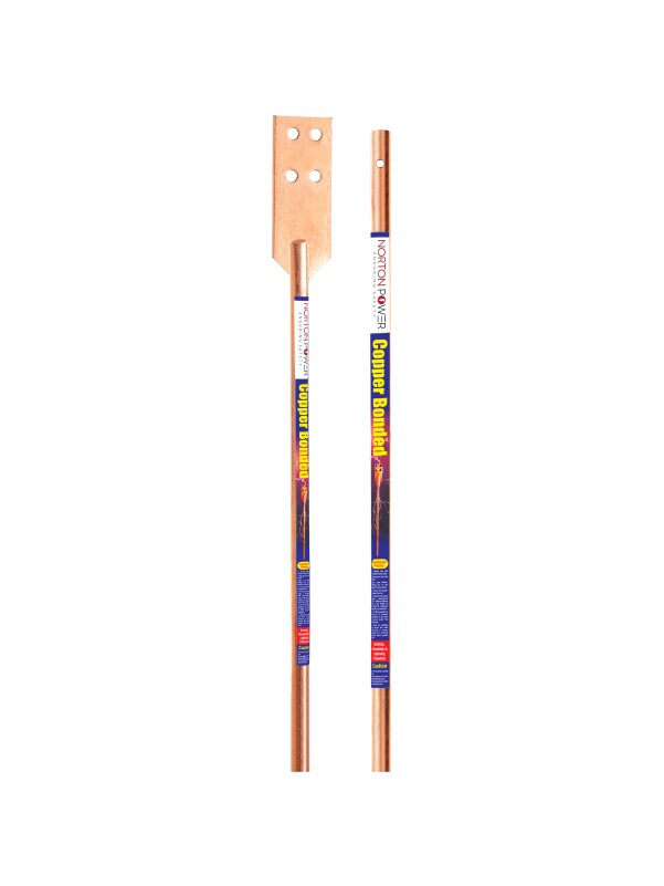
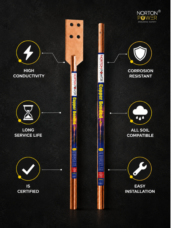
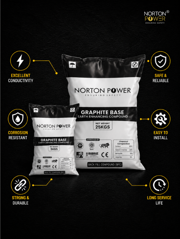
- Dedicated earth pit — copper bonded rod + earth-enhancing compound, target ≤ 10 Ω.
- Test/isolating joint so the earth can be measured independently.
2. Step 1 — mast height and placement
The protection radius under NF C 17-102 depends on the air terminal height above the surface being protected and the device delta-T. Place the mast at the highest practical point and high enough that the calculated radius covers the whole structure. The tip should stand at least 2 m above everything it protects. One correctly placed high mast usually beats several short ones.
3. Step 2 — mount the air terminal
Fix the ESE head to the mast top with the supplied hardware, ensuring solid electrical and mechanical contact. Use a stainless (AISI 316) tip for coastal and industrial atmospheres. Keep the supplier calibration certificate with the project file — it is part of the acceptance dossier.
4. Step 3 — route the down-conductors
NF C 17-102 requires at least two down-conductors from the air terminal to earth, taken by the most direct routes on opposite faces of the structure.
- No sharp bends — surge current will not follow a tight 90° corner; use wide, gentle curves (bend radius ≥ 20 cm).
- Fix the conductor every ~1 m and keep it clear of door frames, windows and gas/water pipes.
- Avoid loops — a loop is an inductor that the surge will jump across, damaging whatever is inside it.
- Bond the down-conductor to any large metal mass it must pass within 0.5 m of.
5. Step 4 — the dedicated earth pit
Each down-conductor terminates in a dedicated earth pit — do not rely on the building earth alone. Drive a 250 µ copper bonded rod, pack it with earth-enhancing compound, and bond the down-conductor in via a test/isolating joint. Target ≤ 10 Ω for the lightning earth (lower is better). On high-resistivity soil, add a second rod or compound to hit it.
6. Step 5 — fit the surge-event counter
Install the lightning strike counter on one down-conductor at ~2 m above ground, in line with the surge path. It records strikes so the owner has a maintenance and insurance record. Note the start reading in the commissioning report.
7. Step 6 — test and commission
- Open the test joint and measure the earth-pit resistance (≤ 10 Ω target) after compound curing.
- Megger / continuity test from the air terminal tip all the way to the earth pit — confirm an unbroken low-resistance path on each down-conductor.
- Record the strike-counter start value, the earth reading, and photograph the mast, routing and pit.
- File the calibration certificate, test readings and as-built drawing as the acceptance dossier.
8. Maintenance
- Annual visual: tip intact, mast vertical, conductors fixed and unbroken, counter readable.
- Annual earth-resistance test at the test joint, logged.
- Inspect after any recorded strike — verify the tip and down-conductor are undamaged.