A solar plant earthing BOM is built from a few core materials: driven electrodes, interconnecting strip, lightning protection, backfill compound and the joints and accessories that tie them together. The quantities scale with the plant MW, the number of inverter and transformer stations, and the soil resistivity.
Core materials
| Material | Role in the plant |
|---|---|
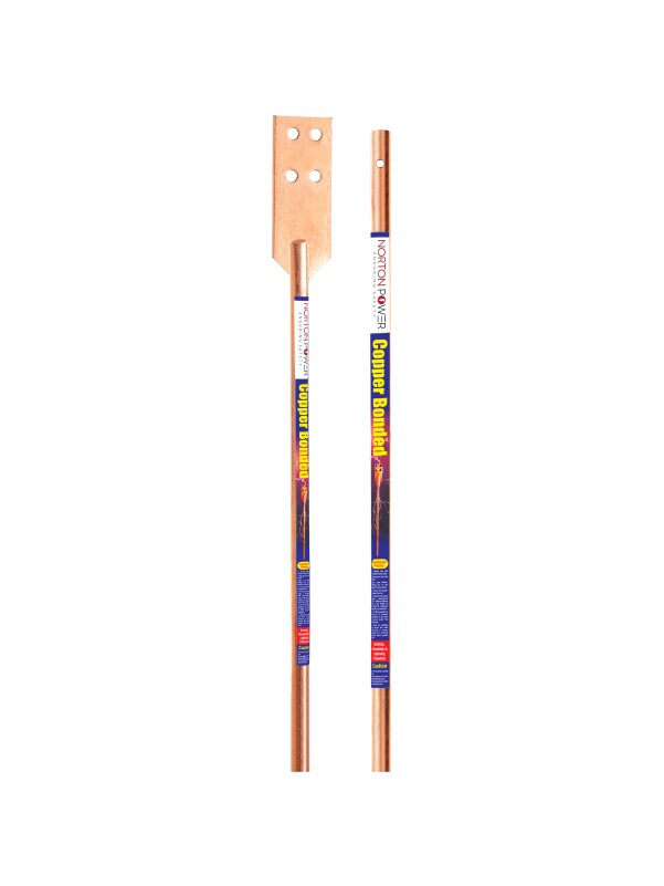
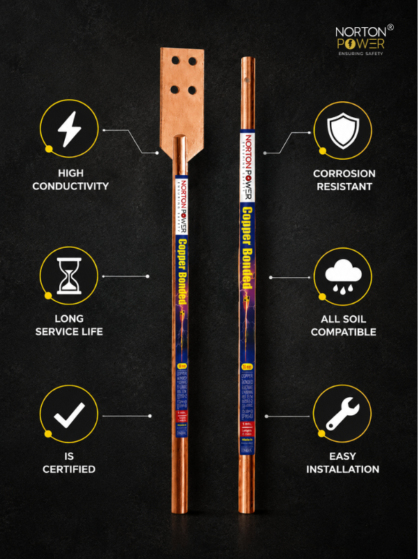
| Copper bonded rods (UL 467) | Driven electrodes along the array and at stations |
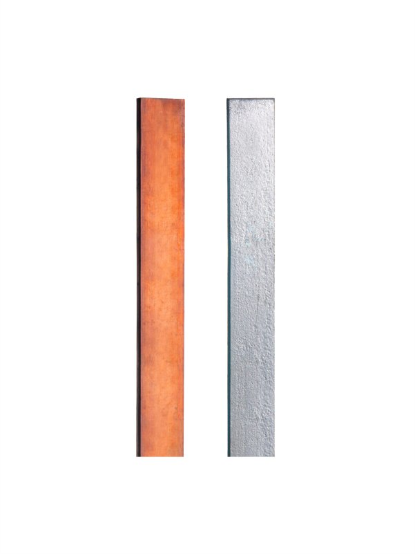
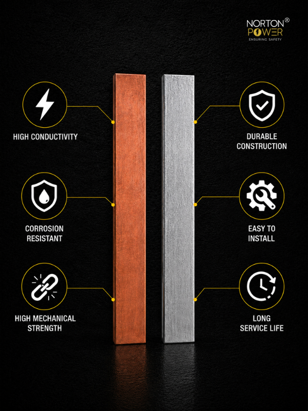
| GI / copper earthing strip | Earth grid, structure and module bonding |
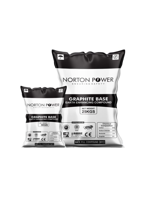
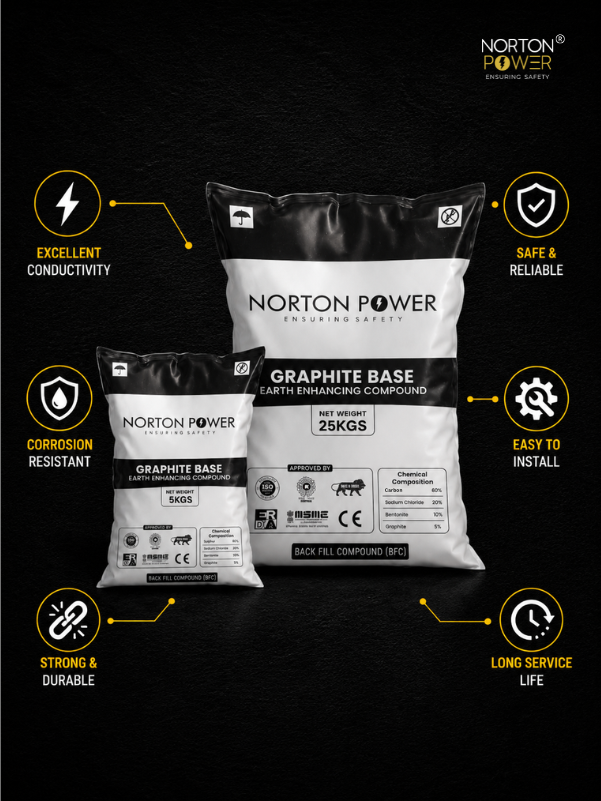
| Earth-enhancing compound | Lowers pit resistance in dry or rocky soil |
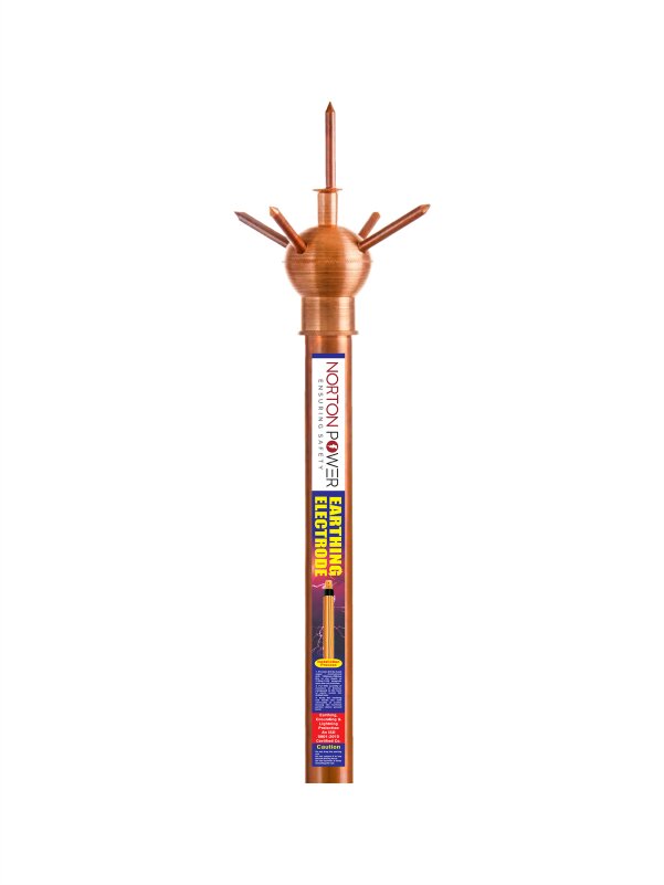
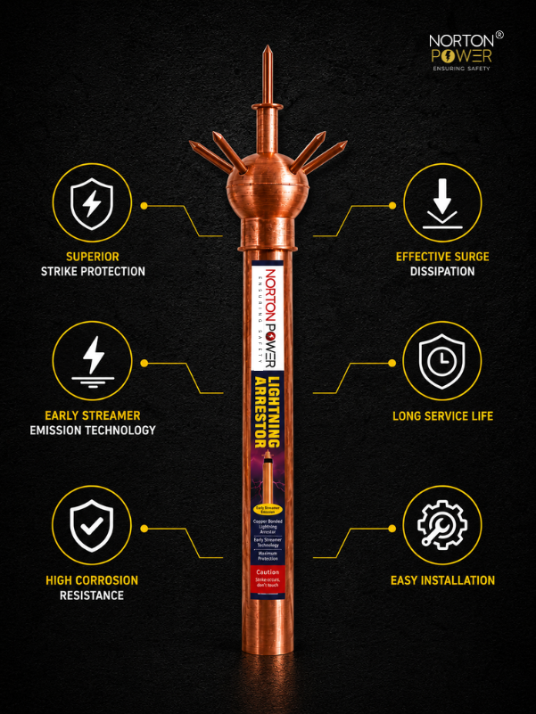
| Lightning arrestors + down-conductor | Protect inverter and control rooms |
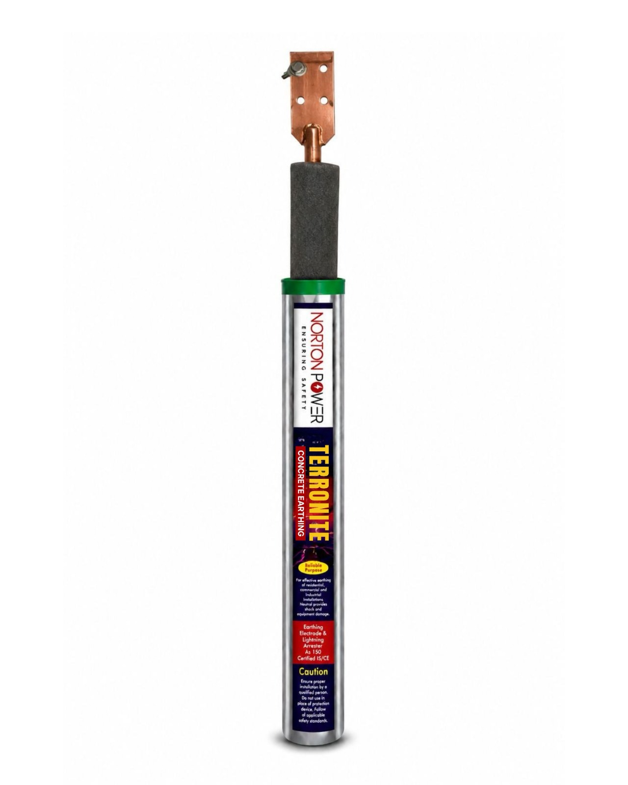
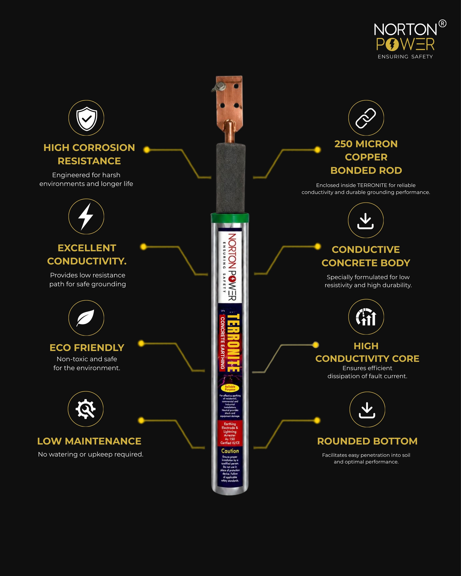
| Conductive-concrete electrode (Terronite) | Permanent low resistance in difficult soil |
| Clamps, lugs, pit covers | Joints, terminations and inspection access |
Sizing the quantities
Rods and strip scale with the array rows and stations; arrestor count with the exposed structures; compound with the number of pits that must hit the resistance target. See the solar power plant earthing design guide for the layout.