A solar plant needs four coordinated earthing systems: equipment (safety) earth for all metalwork, DC earth for the array side, AC earth for inverters and transformers, and lightning protection earth. They are bonded into one low-resistance grid so that no dangerous potential can appear between parts during a fault or a strike.
1. Module and structure earthing
Every module frame bonds to its mounting structure, and each structure row bonds to a buried earth conductor - this is module-to-module and structure earthing. It keeps all exposed metal at the same potential and carries fault and induced current away safely.
2. DC and AC earthing
The DC side (array, combiner boxes, inverter DC) and the AC side (inverter AC, transformer, switchgear) each get their own earth, bonded to the common grid. Keeping separate electrodes for sensitive and power earths, all tied together, avoids noise and ground loops.
3. The earth grid and electrodes
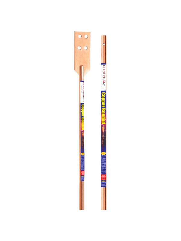
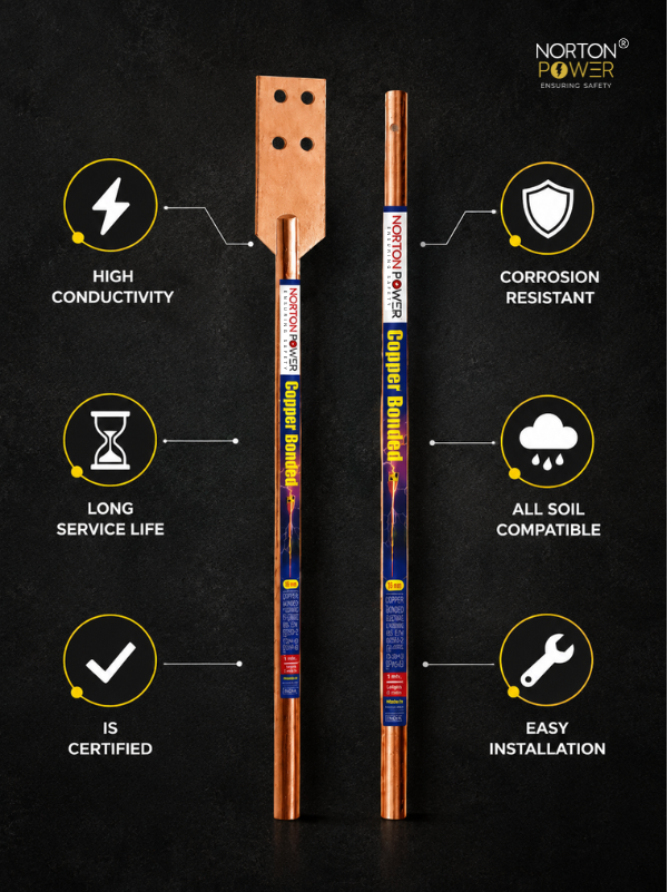
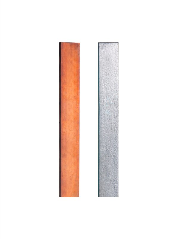
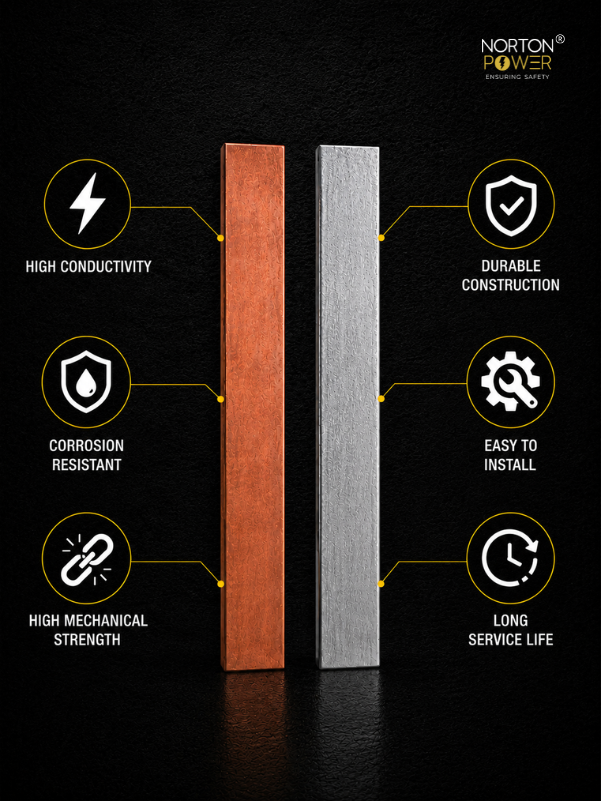
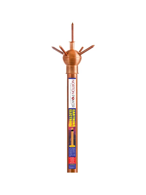
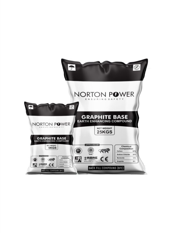
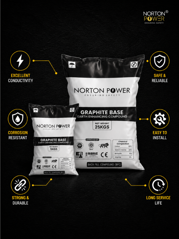
Copper bonded rods are driven along the array and at the inverter and transformer stations, tied with buried GI or copper strip into a grid. The target earth resistance is usually 1 ohm or less at the inverter and transformer; high-resistivity soil needs more rods, deeper driving or earth-enhancing compound.
4. Lightning protection
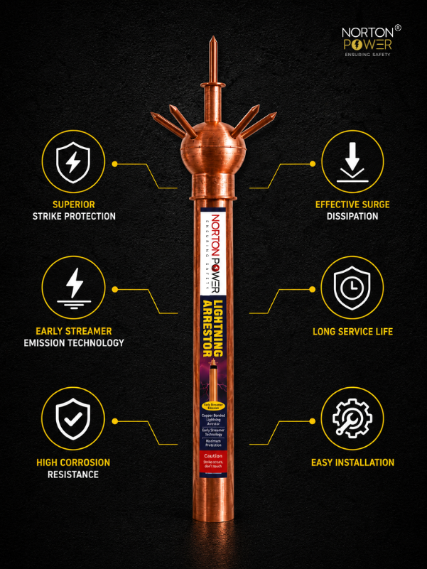
Open solar farms are exposed, so air terminals or masts protect the inverter and control rooms, with down-conductors to a dedicated lightning earth bonded to the main grid. Surge protection devices guard the DC and AC electronics.