A data centre earth has a harder job than a factory earth: besides electrical safety, it has to keep thousands of interconnected IT chassis at the same potential so a fault or surge on one rack does not push current through the data cabling of another. That means a low-impedance, equipotential grounding system, not just a low-resistance earth pit. This guide walks through the design and the bill of materials.
1. The earthing sub-systems in a data centre
| System | Job |
|---|---|
| Electrical safety earth | Bonds every enclosure, drains fault current, trips protection. Per IS 3043 / local code. |
| Signal reference grid (SRG) | A copper mesh under the raised floor keeping all IT equipment at one potential across a wide frequency range — the defining feature of a data-centre earth. |
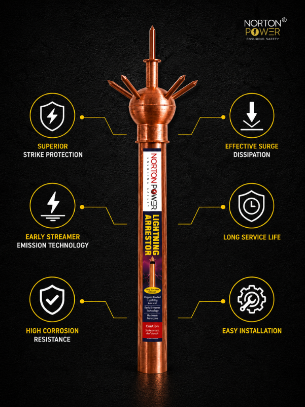
| Lightning + surge protection | Air termination + down-conductors for the building, and SPDs at every power boundary, all bonded to the common earth. |
All three bond to one common earthing point so the whole facility is a single equipotential mass (the IEEE 1100 / IEEE 80 principle).
2. The resistance and impedance targets
A data centre typically specifies a very low earth resistance — commonly ≤ 1 Ω, and ≤ 0.5 Ω for large or Tier III/IV facilities. Just as important is low impedance at high frequency (surge and switching transients are fast), which is why the design uses wide copper strip and a mesh rather than a few long thin conductors.
3. The electrode network
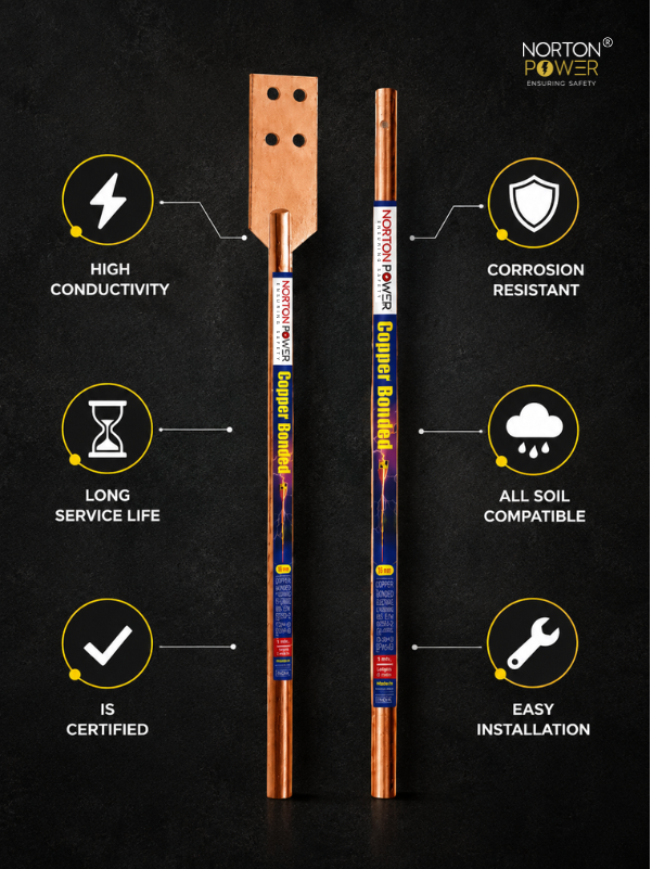
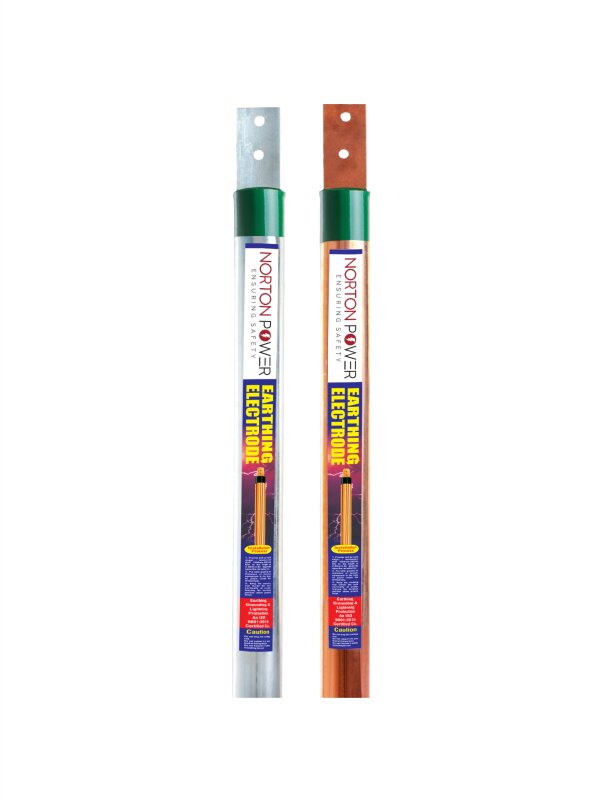
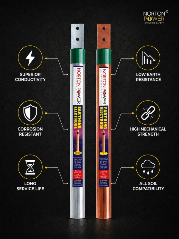
- A perimeter ring of copper bonded 250 µm rods around the building, interconnected by buried copper strip, with earth-enhancing compound per pit to hit the sub-ohm target.
- Multiple rods in parallel (spaced ≥ 2× rod length) — a single-figure ohm target needs many electrodes plus compound.
- A buried copper ring conductor that itself contributes to the resistance and ties the pits into one bus.
- Bonded to the transformer/substation earth so there is one facility earth reference.
4. The signal reference grid
Under the raised floor, a copper conductor grid (typically a 0.6 m to 3 m mesh of copper tape or bonding cable) connects every floor pedestal and bonds each rack to it. This keeps all IT chassis equipotential so induced and fault currents do not travel through data cabling. The SRG bonds to the electrical safety earth at the common earthing point.
5. Surge protection at every boundary
Earthing alone does not stop transients reaching the electronics. Surge protective devices (SPDs) are fitted at the incoming supply, at distribution boards, and at critical equipment, each with a short, low-impedance bond to the common earth. A good earth is what makes an SPD work.
6. Reference bill of materials
| Item | Typical quantity |
|---|---|
| Copper bonded rod, 17 mm × 3 m, 250 µm Cu, UL 467 | 16–24 (perimeter ring) |
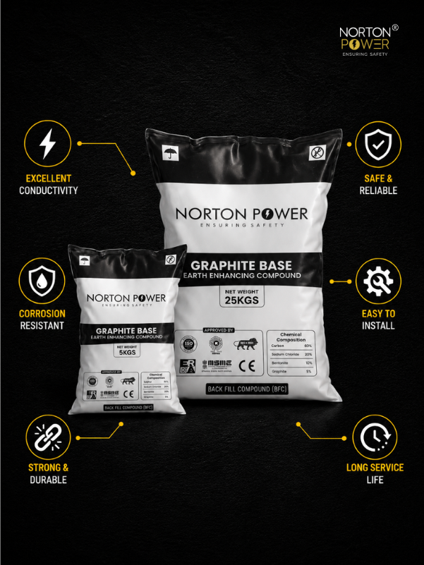
| Earth-enhancing compound, 25 kg bag | 32–48 (2 per pit) |
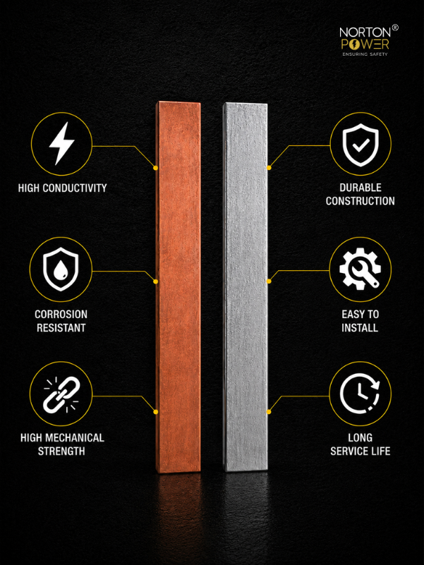
| Copper earthing strip, 25 × 6 mm (ring + risers) | ~200 m |
| Copper tape / bonding conductor for the signal reference grid | per floor area |
| Earth pit chambers + covers (non-conductive SMC) | 16–24 |
| Compression lugs, clamps, bonding hardware | per drawing |
7. Checks before you buy
- Is the electrode ring copper bonded (250 µm) and CPRI-tested, with compound sized to reach ≤ 1 Ω (or ≤ 0.5 Ω)?
- Is a signal reference grid specified, not just perimeter pits?
- Is everything bonded to one common earthing point (safety + SRG + lightning + transformer)?
- Copper throughout for low high-frequency impedance?
- Does the supplier provide a sized BOM against your measured soil resistivity and target?