Solar PV plants present three earthing challenges in one footprint: thousands of metal module frames that must be equipotentially bonded; high-current DC and AC equipment that needs low-impedance ground references; and a large open-area exposure to direct lightning strikes. This guide walks through the design process for a typical 5 MW utility-scale plant in Indian conditions, and ends with the complete BOM.
1. The three earthing systems in a solar plant
| System | Function and standard |
|---|---|
| DC earthing | Inverter DC bus + combiner box earth. Drains DC ground faults to the grid. Per IS 3043 + manufacturer spec. |
| AC earthing | Inverter AC output + transformer LV neutral + LV switchgear earth. Sized for line-to-earth fault current. Per IS 3043 + utility tender spec. |
| Module-frame bonding | Aluminum / galvanised module frames equipotentially bonded to a common earth bus. Mostly for personnel safety (touch potential) but also drains induced currents from nearby lightning strikes. Per IEC 61730. |
All three systems are bonded together at the plant's main earth bus to maintain equipotentiality (the IEEE 80 principle). The total system must achieve a single-figure resistance to remote earth — typically ≤ 1 Ω for a 5 MW plant, ≤ 0.5 Ω for larger or grid-export installations.
2. Start with the soil resistivity survey
Before any sizing, get a Wenner 4-pin soil resistivity survey across the plant footprint at multiple depths (1 m, 3 m, 6 m). Solar sites are often on uneven, mixed-soil terrain — a single point measurement is misleading. Take readings at the corners and centre.
Typical Indian solar plant soil resistivity values:
| Soil type / region | ρ in Ω·m (peak summer) |
|---|---|
| Black cotton soil (Maharashtra, Gujarat) | 20–60 |
| Sandy loam (Rajasthan, Gujarat coast) | 80–200 |
| Lateritic / red soil (Karnataka, AP) | 150–400 |
| Rocky / mountainous (Himalayan, Tier-2 hill sites) | 500–2000+ |
| Saline / coastal (Tamil Nadu coast, Kutch) | 30–80 (but corrosive) |
3. Earth electrode network design
Per-string-inverter pit
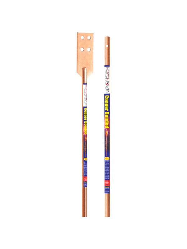
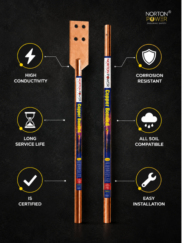
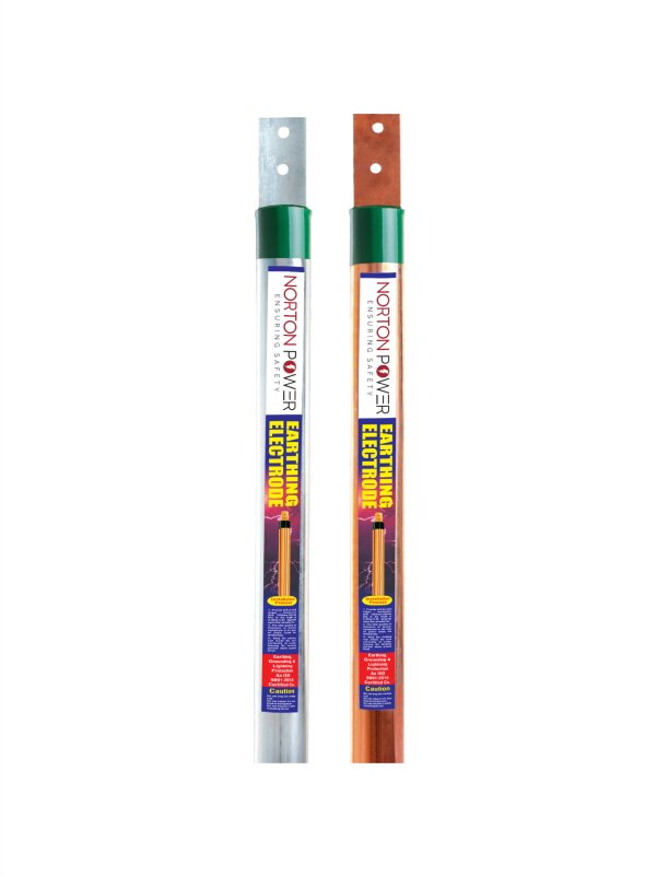
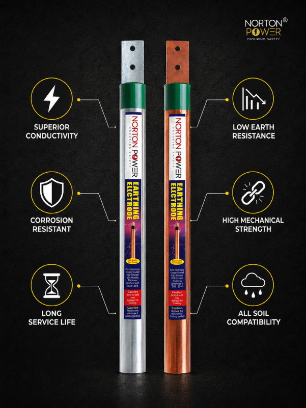
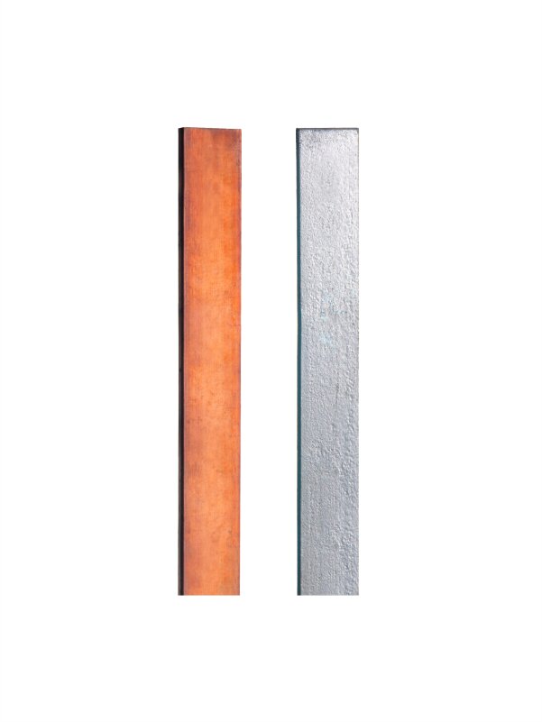
Each string inverter (typically 100–250 kW) gets its own dedicated earth pit beneath or adjacent to the inverter pad. Spec: 17 mm × 3 m copper bonded rod with 250 µ Cu coating, earth-enhancing compound, 25×6 mm Cu strip to the inverter earth terminal.
Central inverter pit (for plants with central inverters)
Central inverters (1–4 MW each) need higher-capacity grounding: minimum 4 rods in parallel, 6 m apart, each with EE compound, connected via a buried 50×6 mm Cu strip into a single bus terminating at the inverter earth bar.
Transformer earth pit
The plant transformer (typically 5–10 MVA for a 5 MW plant) has its own earthing requirement: neutral earth + body earth. Each is a dedicated multi-rod pit per IS 3043 substation guidelines. Total transformer earth resistance ≤ 0.5 Ω.
Module-frame bonding grid
Each module row's aluminum frames are connected via copper bonding clamps (typically 6 mm² Cu wire or 6 mm Cu strip). Adjacent rows are connected to each other and back to a perimeter Cu strip that bonds into the main earth bus. This grid does NOT need to achieve low resistance to remote earth — its job is equipotentiality. A few ohms is acceptable.
4. Lightning protection
Solar plants are large open footprints — high exposure to direct lightning strikes. Two design philosophies are used in India:
Conventional (IEC 62305)
Franklin rods mounted on the inverter pad / module-row support posts at regular intervals. Multiple masts per plot. Each connects to the earth network via a dedicated down-conductor (25×3 mm Cu strip).
ESE (NF C 17-102)
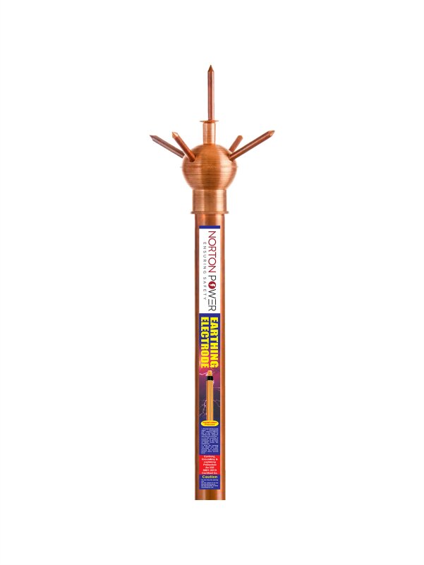
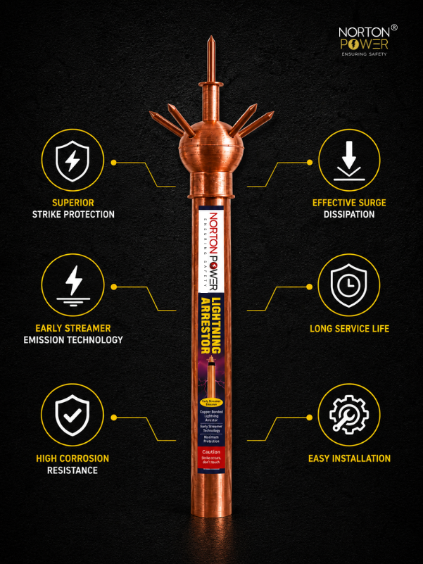
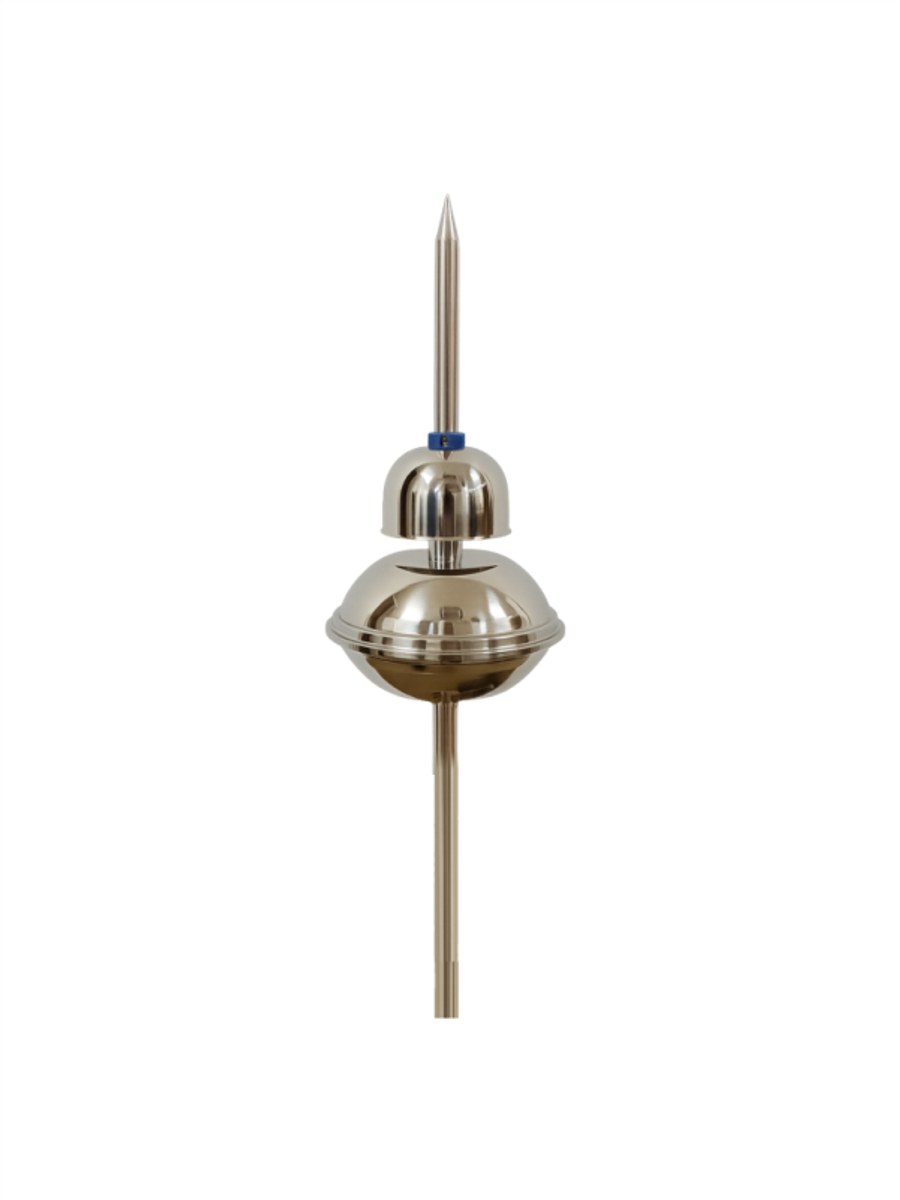
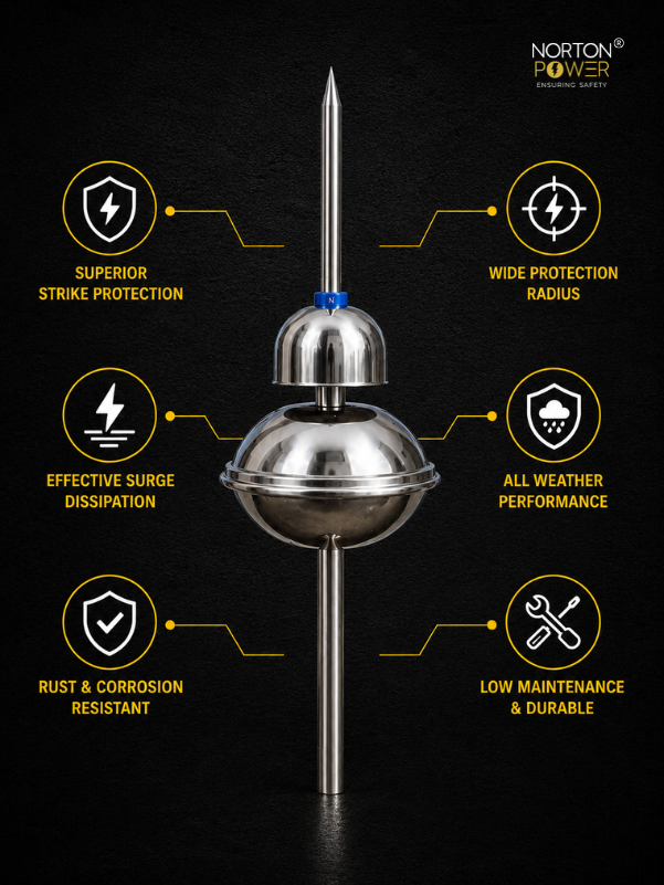
1–4 ESE arrestors on tall masts (10–12 m above plant ground level), each covering a 50–70 m radius depending on delta-T rating. Significantly fewer masts than the conventional approach. Each mast connects to a dedicated earth pit. The cost-saving on masts + down-conductors usually exceeds the ESE unit premium for plants ≥ 5 MW.
We have a separate article on the ESE vs conventional choice — for solar plants ≥ 5 MW, ESE is typically the more economical choice if the project allows NF C 17-102 spec.
5. Reference BOM for a 5 MW plant
Sample BOM for a 5 MW solar plant with 25 string inverters, 1 central transformer, and 2 ESE lightning arrestors. Sandy loam soil at ρ = 100 Ω·m, target main earth resistance ≤ 1 Ω.
| Item | Quantity |
|---|---|
| Copper bonded rod, 17 mm × 3 m, 250 µ Cu, UL 467 | 50 (1 per inverter pit + 4 per central pit + 8 for transformer + 8 for ESE base + 5 spare) |
| Pit cover, 450×450 mm, SMC (non-conductive) | 40 |
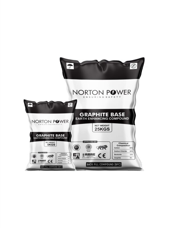
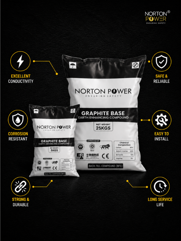
| Earth-enhancing compound, 25 kg bag | 100 (2 per pit) |
| Earthing strip, 25×6 mm Cu | ~400 m (interconnections + perimeter) |
| Earthing strip, 50×6 mm Cu (HV grid) | ~120 m (transformer + ESE down-conductors) |
| ESE lightning arrestor, 40 µs delta-T | 2 |
| Lightning mast, 12 m galvanised | 2 |
| Module-frame bonding clamps + Cu wire | ~5000 (one per module + interconnects) |
| Compression lugs, U-bolts, clamps | as per drawing |
| Earth-resistance commissioning tester rental | 1 day |
6. Commissioning
Per IS 3043 and CEIG / DISCOM tender specs, commissioning involves:
- Wait 7 days post-pit-closure for compound curing.
- Measure each pit's individual resistance — log all values.
- Measure overall plant earth resistance from the main earth bus to remote earth — must meet ≤ 1 Ω target.
- Measure step-and-touch voltage at the perimeter (per IEEE 80) — must be within safe limits for personnel.
- Megger test the down-conductors of lightning arrestors — continuity from arrestor tip to earth pit.
- Submit the commissioning report with all readings + photographs of pit construction stages.