The earthing strip is the conductor that ties electrodes, equipment and the lightning system into one equipotential mass. Undersize it and it becomes the weak link — it can overheat and fail during the very fault it exists to carry. This guide shows how to size it properly and what to check before buying.
1. What the strip does
The earthing strip (flat bar / tape) interconnects earth rods into a grid, bonds equipment frames and neutrals to that grid, and carries lightning down-conductor current to the pits. It must carry the prospective fault current for the fault-clearing time without exceeding a safe temperature, and survive decades of buried corrosion.
2. Copper vs GI
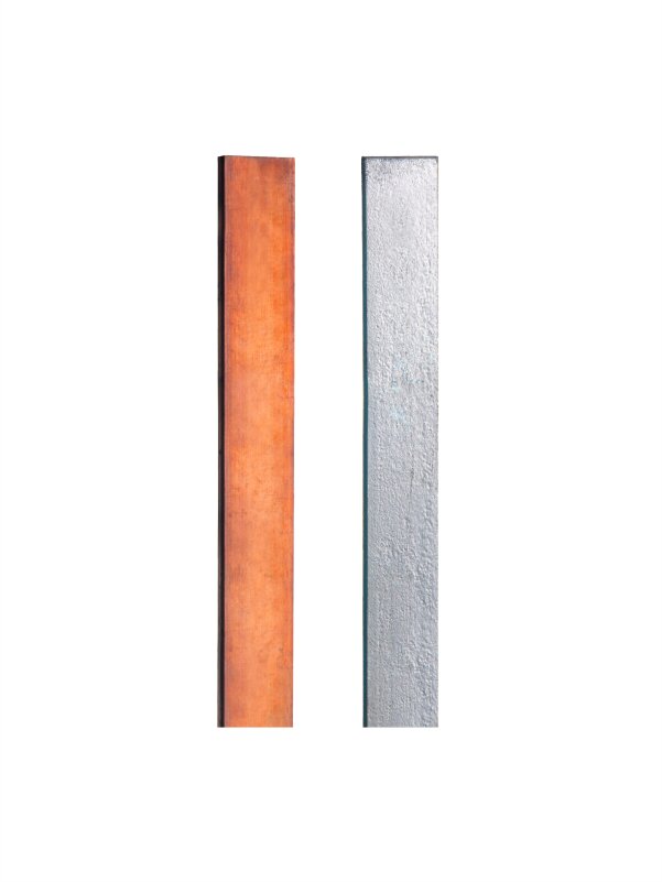
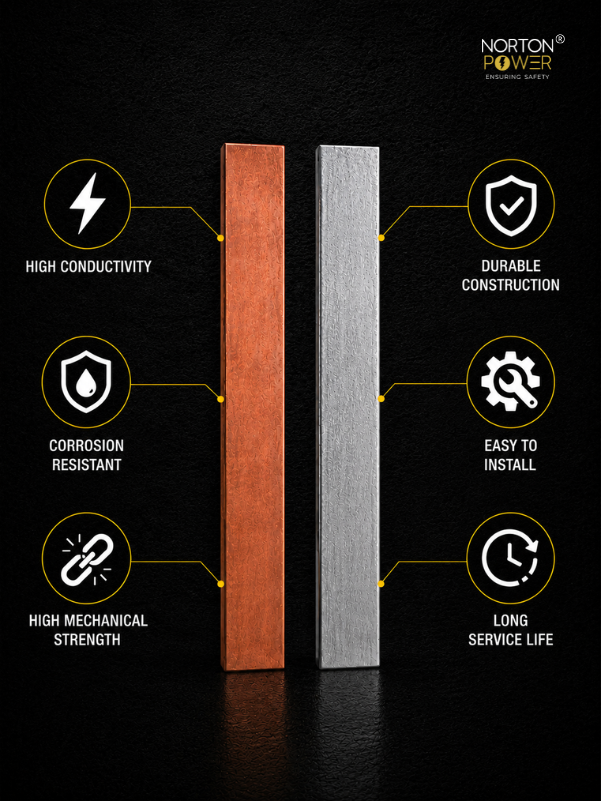
| Attribute | Copper strip · vs · GI strip |
|---|---|
| Conductivity | Highest · vs · ~15–20% of copper |
| Cross-section for same fault rating | Smaller · vs · Larger (to compensate conductivity) |
| Corrosion life in soil | Decades · vs · Shorter; zinc depletes |
| Cost per metre | Higher · vs · Lower |
| Best use | HV grids, lightning down-conductors, long-life infra · vs · Distribution-grade, budget, benign soil |
Copper is the default for substations, solar HV grids and lightning down-conductors. GI is acceptable for distribution-grade work in benign soil where budget is the binding constraint — sized up to compensate for its lower conductivity.
3. Cross-section — let the fault current decide
The minimum cross-section comes from the adiabatic thermal-withstand relationship in IS 3043 / IEC 60949: the conductor must carry the prospective fault current for the protection clearing time without exceeding its limit temperature.
S = (I × √t) / k
where S = cross-section (mm²), I = fault current (A), t = fault clearing time (s), and k is a material constant (≈ 143 for copper, ≈ 80 for steel/GI, for typical limit temperatures). The takeaway: higher fault current or slower protection means more copper — and GI needs roughly 1.8× the copper cross-section for the same duty.
4. Common sizes
| Strip | Typical use |
|---|---|
| 25×3 mm copper | Lightning down-conductor, small equipment bonding |
| 25×6 mm copper | Standard equipment earthing, moderate fault grids |
| 32×6 / 40×6 mm copper | Substation main grids, higher fault current |
| 50×6 mm GI | Distribution-grade grids, budget installations |
| 65×8 / 75×10 mm GI | High-fault GI grids (sized up for conductivity) |
5. Burial, routing and joints
- Bury the grid strip at ~0.5 m depth so it contributes its own soil contact to the earth resistance.
- Use gentle curves, not sharp bends, on any run that carries surge/lightning current.
- Joints must be bolted with the correct lugs / clamps, or exothermically welded for buried HV grids — a loose joint is a hot-spot and a corrosion start point.
- Protect copper-to-GI and copper-to-aluminium joints against galvanic corrosion (bi-metallic washers / appropriate connectors).
6. Checks before you buy
- Copper or GI — does it match the site life and fault duty?
- Is the cross-section sized for the actual fault current × clearing time (not a default size)?
- Material grade and purity (electrolytic copper / IS 4759 GI)?
- Cut lengths or coils, and what jointing hardware / lugs are supplied?
- For GI: coating thickness and corrosion warranty for your soil?