This is the practical procedure used by EPCs and electrical contractors across India for a single 3-metre copper bonded earthing pit, prepared with earth-enhancing compound and tested per IS 3043:2018 acceptance criteria. The sequence is the same whether you are installing one pit or sixteen — only the spacing and grid-strip routing change.
1. Tools and materials
Materials
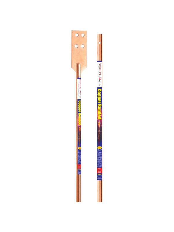
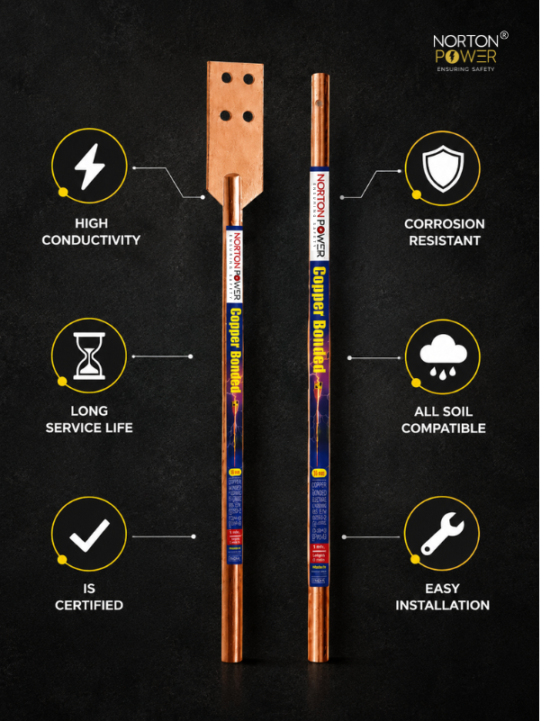
- Copper bonded rod (typical: 17 mm × 3 m, 250 µ Cu coating, UL 467)
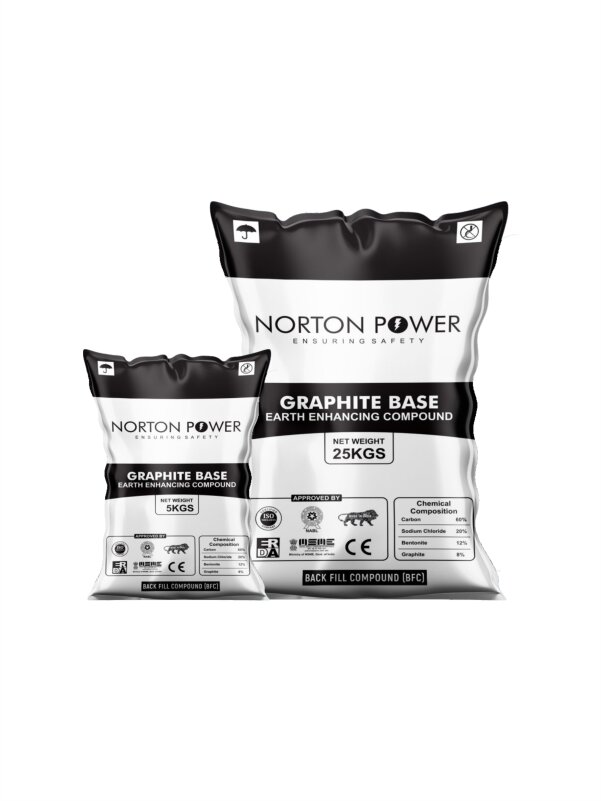
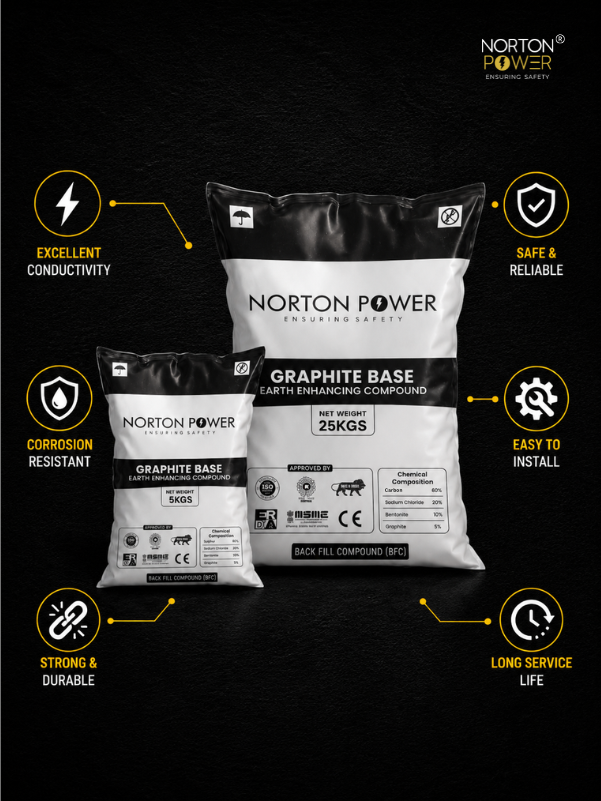
- Earth-enhancing compound (graphite-based, 25 kg bag — one bag per pit)
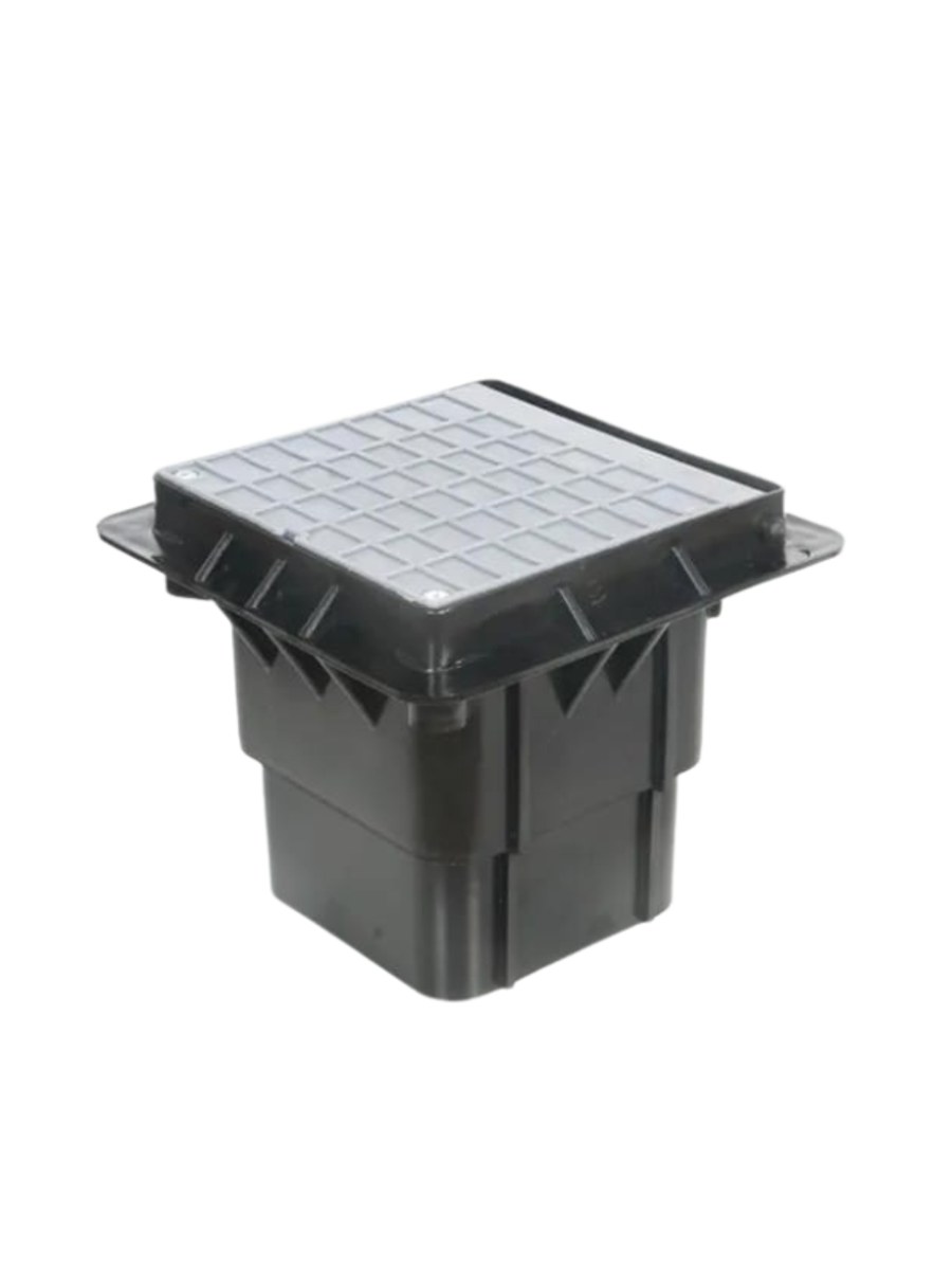
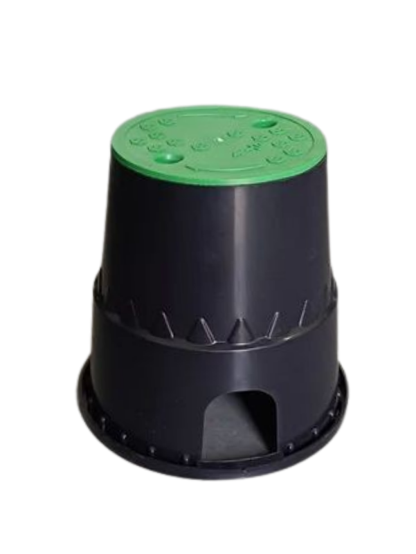
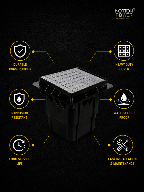
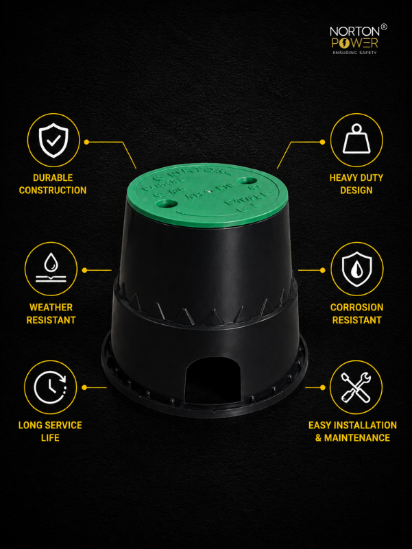
- Pit cover and frame (300×300 mm or 450×450 mm, CI / GI / SMC per loading)
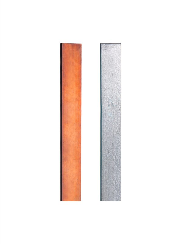
- Earthing strip (typically 25×6 mm Cu or 50×6 mm GI), length per layout
- Connecting lug + clamp / U-bolt for rod-to-strip termination
- Driving cap (protects the rod top during hammering)
Tools
- Earth-pit auger or excavator (digs to 3.5 m depth, 300 mm dia or rectangular 300×300 mm)
- Sledge hammer or pneumatic post-driver (preferred for clean drive)
- Buckets for water (5–10 litres per pit for compound activation)
- Wenner 4-pin earth resistance tester (commissioning)
- Insulated wrenches, hand tools, PPE (safety boots, gloves, hard hat)
2. Pit construction sequence
Step 1: Site selection and marking
Place pits at least 6 m apart (2 × rod length) to avoid mutual interference. Avoid running them directly under the equipment foundation. For a substation grid, the pits should be on the outer perimeter or in dedicated trenches with strip conductors connecting them. Mark the pit boundaries before excavation.
Step 2: Excavation
Excavate to 3.5 m depth (allowing 500 mm cover above the rod top). Pit cross-section is typically 300×300 mm for a single rod, larger if multiple rods will share the pit. Keep the excavated soil aside — half of it will be mixed with the compound and repacked.
Step 3: Rod placement and driving
Lower the rod into the pit with the threaded/connection end at the top. Fit a driving cap to protect the threads. Drive the rod vertically into the pit floor using a sledge hammer or pneumatic driver. The rod should be driven such that its top sits ~500 mm below the finished ground level — that leaves enough headroom for the connection and the pit chamber. Verify verticality with a spirit level during driving.
Step 4: Compound preparation and packing
Mix one 25 kg bag of earth-enhancing compound with half the excavated soil (volume ratio roughly 1:1 by hand). Add water as you mix — the compound is hygroscopic and should reach a moist, kneadable consistency (similar to wet sand). Pour the mixture around the rod, filling the pit cavity in 200–300 mm layers. Tamp each layer lightly before adding the next.
Add an additional 5–10 litres of water at the top to activate the compound's water-retention properties. Compound takes 5–7 days to fully cure into a stable conductive gel; commissioning resistance tests done before curing will read higher than the final stabilised value.
Step 5: Strip connection
Attach the earthing strip to the rod top using a compression lug + bolted clamp or a U-bolt termination. Strip should be torqued to manufacturer spec (typically 12–18 Nm for the standard hardware). Run the strip from the rod, up through the pit chamber wall, to the equipment / grid connection point.
For multi-rod grids, run a continuous strip from rod to rod and back to a common bus. Avoid sharp 90° bends — use gentle curves so surge currents have low impedance paths.
Step 6: Pit chamber and cover seating
Set the pit cover frame on a thin cement bed at ground level, aligned with the rod connection. Backfill around the frame with the remaining excavated soil. Place the pit cover. Mark each pit with a paint stencil or tag for inspection identification (Pit-A1, Pit-A2, etc., matching the layout drawing).
3. Commissioning resistance test
Per IS 3043:2018 Annex C, commission the pit with a Wenner 4-pin earth resistance tester (or equivalent clamp-on tester for live grid measurements):
- Wait 5–7 days after pit closure for the compound to cure.
- Disconnect the rod from any connected equipment (or use a clamp-on tester that isolates).
- Drive the test probes per the tester instructions (typically a current electrode 20 m and potential electrode 12 m from the rod under test).
- Take three measurements and average. The resistance should be ≤ 1 Ω for substation grade, ≤ 5 Ω for industrial distribution, ≤ 10 Ω for residential, per IS 3043.
- If the value is higher than target: add a second rod in parallel at 6 m spacing, or increase compound (re-open the pit, add a second 25 kg bag), then re-test.
4. Ongoing maintenance
- Annual visual inspection: pit cover intact, no signs of erosion or water-logging, connection clamp tight.
- Annual resistance test (especially before monsoon season to baseline) — record in the maintenance log per IS 3043.
- If resistance drifts upward by > 20% from commissioning value, the compound may need re-watering or supplementing — open the pit, add water + ½ bag of compound, repack.