This is a worked example — the kind of calculation a 2-year electrical engineer should be able to do without leaving their desk. The substation is a 500 kVA, 11 kV / 433 V distribution unit on a Tier-2 city industrial plot. The design follows IS 3043:2018.
1. Inputs
| Parameter | Value |
|---|---|
| Substation rating | 500 kVA, 11 kV / 433 V, Dyn11 |
| Maximum fault current (1 s) | 21 kA |
| Required earth resistance (IS 3043 for substation ≤ 11 kV) | ≤ 1 Ω |
| Soil resistivity at 1-3 m depth (typical clay loam, post-monsoon) | ρ = 75 Ω·m |
| Soil resistivity at 1-3 m depth (peak summer) | ρ = 150 Ω·m |
| Design ρ (worst case used for sizing) | ρ = 150 Ω·m |
Two things to note. First, IS 3043 lets you use the design soil resistivity that accounts for seasonal variation — pick the worst-case value. Second, the 1 Ω target is the IS 3043 maximum for an 11 kV substation; some utilities (MSETCL, BSES) tender at ≤ 0.5 Ω for the same rating, so always confirm with the offtaker.
2. Resistance of a single rod
For a vertical rod of length L meters and radius a meters driven into soil of resistivity ρ Ω·m, the textbook formula (Sunde / Dwight, used in IS 3043 Annex C):
R₁ = (ρ / 2πL) × ln(8L / d - 1)
where d is the rod diameter in meters.
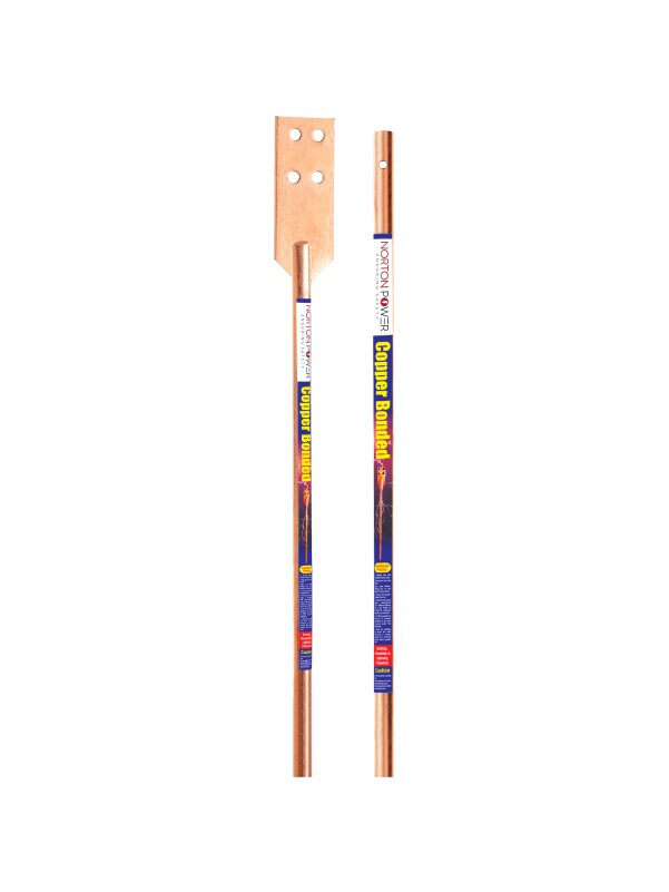
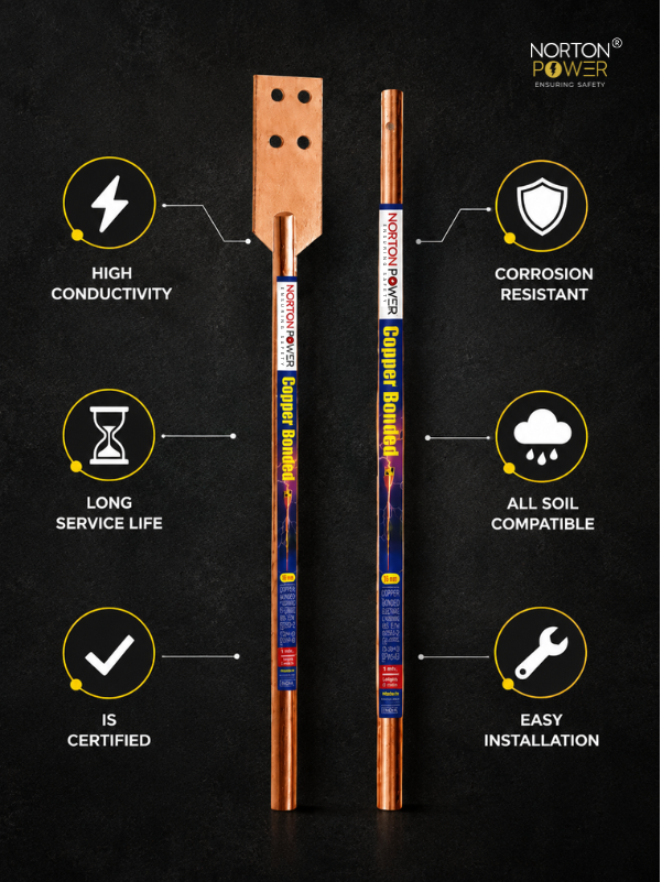
Plugging in a Norton Power 17.2 mm × 3 m copper-bonded rod (d = 0.0172 m, L = 3 m, ρ = 150 Ω·m):
- 8L / d = 24 / 0.0172 = 1395
- ln(1395 - 1) = ln(1394) = 7.24
- R₁ = (150 / (2π × 3)) × 7.24 = (150 / 18.85) × 7.24 = 57.6 Ω
One rod gets us 57.6 Ω. We need ≤ 1 Ω. So we need a multi-electrode arrangement.
3. Multi-rod grid
Rods in parallel have a combined resistance that’s lower than R₁/N because of mutual interference between the rods’ electric fields. The Schwarz formula approximation for N identical rods spaced 2L apart in a straight line:
R_N ≈ R₁ × (1 + (αₙ × (N - 1))) / N
where αₙ is the rod-interference factor (≈ 0.7 for rods spaced ~2L apart).
Required N for R_N = 1 Ω:
| N rods | Computed R_N |
|---|---|
| 2 | ~34.6 Ω |
| 4 | ~17.3 Ω |
| 8 | ~8.7 Ω |
| 16 | ~4.5 Ω |
| 32 | ~2.3 Ω |
| 64 | ~1.2 Ω |
32 rods at 3 m each barely scrapes 2 Ω; 64 rods is impractical on a substation footprint. The straight-rod-only approach won’t hit our target. This is where earth-enhancing compound and a grid with strip conductors enter the calculation.
4. Earth-enhancing compound reduces effective ρ
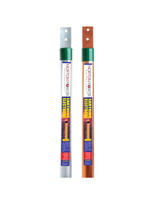
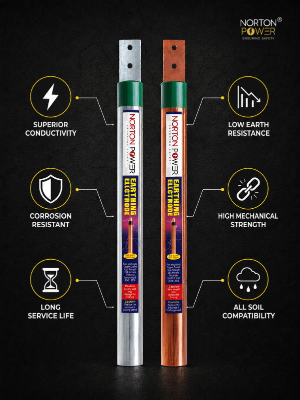
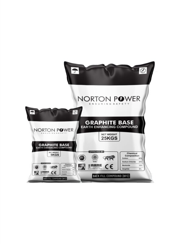
A graphite-based earth-enhancing compound surrounding each electrode reduces the apparent soil resistivity in the immediate vicinity of the rod from ρ = 150 Ω·m to roughly ρₑff = 25-40 Ω·m (manufacturer-dependent; assume 35 Ω·m for the conservative case).
Recomputing R₁ with ρₑff = 35 Ω·m:
R₁ = (35 / 18.85) × 7.24 = 13.4 Ω
Now the multi-rod table redraws:
| N rods (with EE compound) | Computed R_N |
|---|---|
| 2 | ~8.0 Ω |
| 4 | ~4.0 Ω |
| 8 | ~2.0 Ω |
| 12 | ~1.4 Ω |
| 16 | ~1.05 Ω |
| 20 | ~0.85 Ω |
16 rods + EE compound gets us to ~1.05 Ω — within tolerance of the 1 Ω target. 20 rods would give a safety margin and easily meet the stricter 0.5 Ω target.
5. Grid strip conductor reduces resistance further
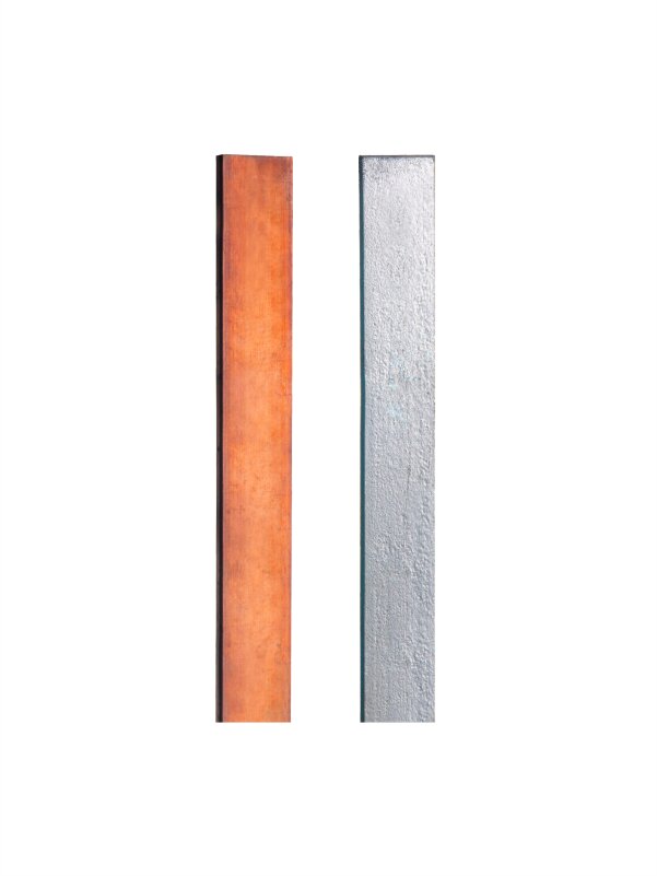
Connecting all rods with a buried copper or GI earthing strip (typically 25 × 6 mm copper or 50 × 6 mm GI) adds another parallel earthing component — the strip itself contributes to the resistance reduction via its surface contact with the soil along its full length.
For a 50 m run of 25 × 6 mm copper strip buried at 0.5 m depth in ρ = 150 Ω·m soil, the strip’s standalone resistance is roughly 4-5 Ω. In parallel with the 16-rod grid (1.05 Ω), the combined resistance becomes:
R = (R_rods × R_strip) / (R_rods + R_strip) = (1.05 × 4.5) / (1.05 + 4.5) = 0.85 Ω
Final design value: 0.85 Ω. Meets IS 3043, meets MSETCL/BSES stricter tender values, and has a 15-20% margin against seasonal soil-resistivity drift.
6. Final bill of materials
| Item | Quantity |
|---|---|
| Copper bonded rod, 17.2 mm × 3 m, 250 µm Cu, UL 467 | 16 |
| Earth pit chamber + cover (300×300 mm), CI or SMC | 16 |
| Earth-enhancing compound, 25 kg bag | 32 (2 per pit) |
| Copper earthing strip, 25 × 6 mm, length per layout | ~50 m |
| Compression lugs / clamps for rod-to-strip connection | 16 sets |
| Riser pipe and identification labels | as per drawing |
This BOM is what a typical Norton Power quotation looks like for a 500 kVA substation tender. Lead time on the rods + EE compound + strip is 14-18 days, with dispatch from Raipur to most Tier-2 cities by road freight.
7. Final sanity checks before installation
- Re-measure soil resistivity at the actual pit locations (Wenner 4-pin method) before mass excavation. Soils can vary across a single substation plot.
- Pit spacing ≥ 2 × rod length to avoid mutual interference. For 3 m rods that means ≥ 6 m spacing.
- Avoid placing the earthing grid directly under the substation building or transformer foundation — keep a 1-2 m perimeter offset.
- Connect the neutral, equipment earth, and lightning protection down-conductor to the same grid (a single equipotential bonded mass).
- Commission with a clamp-on earth-resistance tester immediately after EE-compound curing (5-7 days post-water activation).