A telecom tower is a tall metal structure full of sensitive electronics standing alone in an open field — the single most lightning-exposed asset in most networks. Its earthing system does two jobs at once: drain direct lightning strikes safely to ground, and hold a low, stable earth reference so the radios and rectifiers survive. This guide covers how to design that system and what goes into a tower earthing bill of materials.
1. Why tower earthing is a special case
- The tower itself is a lightning receptor — strikes are expected, not rare, so the down-path and earth must carry full lightning current without rising to a dangerous potential.
- Sensitive DC and RF equipment shares the site — a poor earth lets surge and ground-potential-rise damage rectifiers, BTS units and feeders.
- Sites are often remote and on high-resistivity ground (hilltops, dry or rocky soil), where a plain driven rod cannot reach the target resistance.
- Maintenance visits are expensive, so the earth must be stable and effectively maintenance-free.
2. The earthing system: one equipotential mass
The goal is a single bonded earth to which everything connects, so there is no voltage difference between parts during a strike:
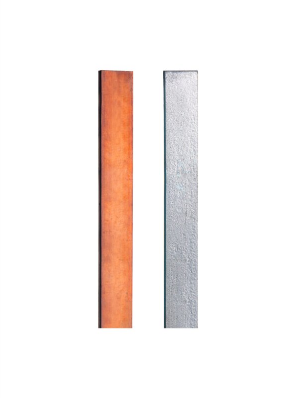
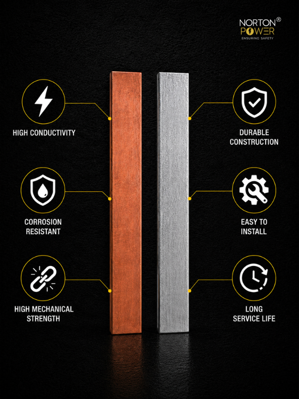
- Tower-foot earthing: a rod pit at each tower leg, interconnected by a buried ring conductor (25×6 mm copper or 50×6 mm GI strip).
- Equipment / shelter earth: a separate rod pit for the equipment room earth bar, bonded back to the tower ring.
- Ring earth electrode: the buried ring ties all pits together and lowers the combined resistance.
- Bonding: tower body, waveguide/feeder entry (via a bonding bar), lightning down-path and equipment earth all bond to the same mass.
3. Lightning protection at the top
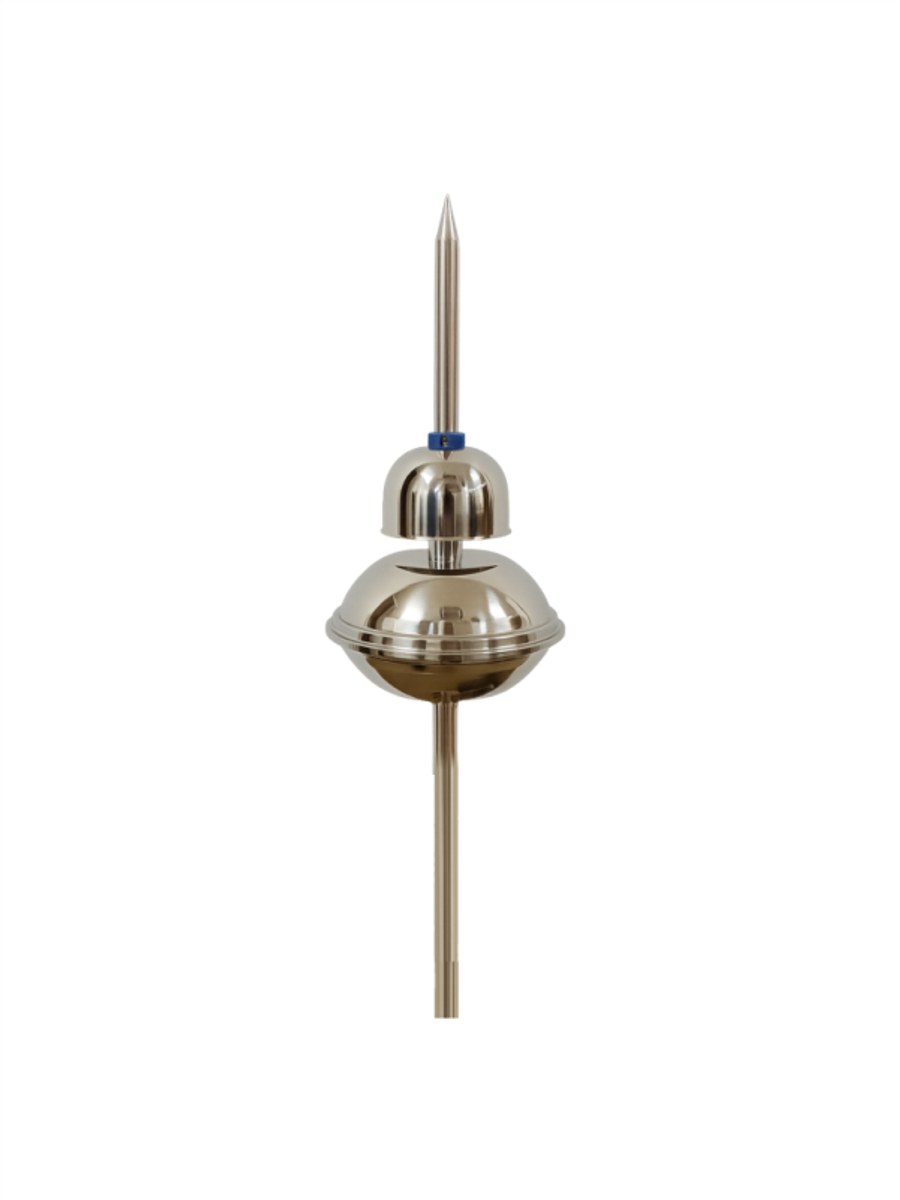
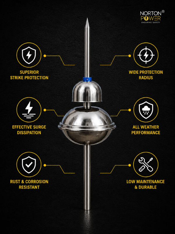
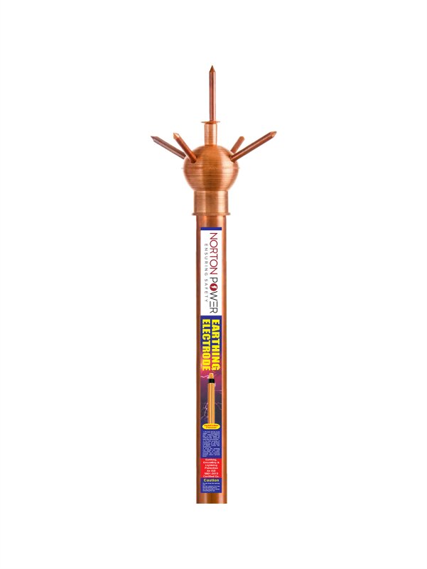
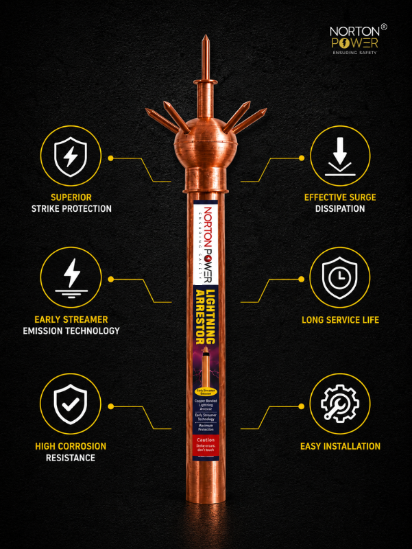
The tower structure carries most strikes, but a dedicated air terminal at the peak protects the top-mounted antennas and gives the current a defined path. On tall towers a conventional (Franklin) finial bonded to the tower steel is standard; for a compound with several short structures around the tower, an ESE arrestor on the tower can extend a protected radius over the whole site under NF C 17-102. Down-conductors run the tower steel itself plus a dedicated copper down-conductor to the ring.
4. Hitting the resistance target on bad soil
Tower specs typically demand a low earth resistance (often ≤ 5 Ω, and ≤ 2 Ω for critical sites). On high-resistivity hilltop or dry soil a bare rod cannot get there. The levers, in order:
| Situation | Answer |
|---|---|
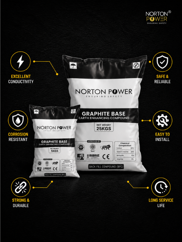
| Moderate soil | Copper bonded 250 µm rods in a ring + earth-enhancing compound per pit. |
| High-resistivity / dry soil | More rods on the ring + compound; extend the ring conductor for surface contact. |
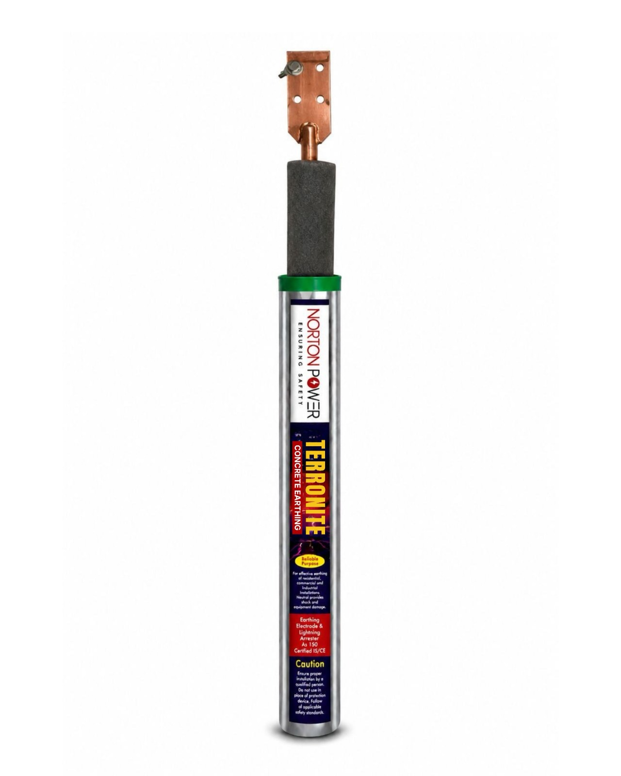
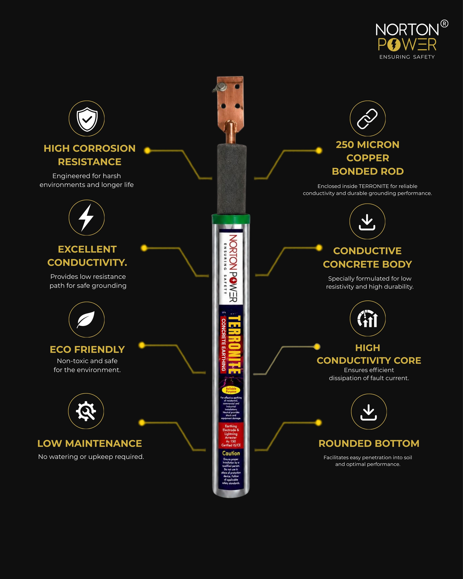
| Rock / very high resistivity | Conductive-concrete earthing electrodes (IEC 62561-7), installed vertically or in a horizontal trench where rock stops depth. |
5. Reference bill of materials (single tower)
| Item | Typical quantity |
|---|---|
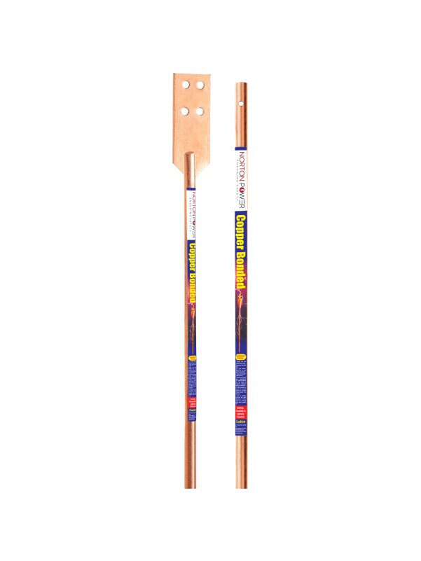
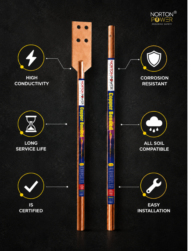
| Copper bonded rod, 17 mm × 3 m, 250 µm Cu, UL 467 | 6–8 (tower legs + equipment + spare) |
| Earth-enhancing compound, 25 kg bag | 8–12 (1–2 per pit) |
| Earthing strip, 25 × 6 mm copper (ring + bonding) | ~60–100 m |
| Air terminal / finial (or ESE arrestor for a compound) | 1 |
| Down-conductor, 25 × 3 mm copper tape | tower height + routing |
| Earth pit chambers + covers | 6–8 |
| Bonding bar, lugs, clamps | per drawing |
| Conductive-concrete electrode (rocky sites only) | as required |
6. Checks before you buy
- Measure soil resistivity at the actual site (Wenner 4-pin) — tower sites vary wildly.
- Is every rod copper bonded with a specified micron rating (not "copper bonded" alone) and CPRI-tested?
- Is the design one bonded equipotential mass (tower + equipment + lightning on the same earth)?
- For remote / rocky sites, is a maintenance-free option (compound or conductive concrete) included?
- Does the supplier give a sized BOM for your resistance target?